SensGuard Alarm System User Manual
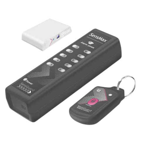
Sensors operate on built-in battery. This battery provides sensor’s life cycle for more than 5 years.
The system consists of 3 main components:
- Wireless optical sensors.
- The alarm unit.
- The system control keychain.
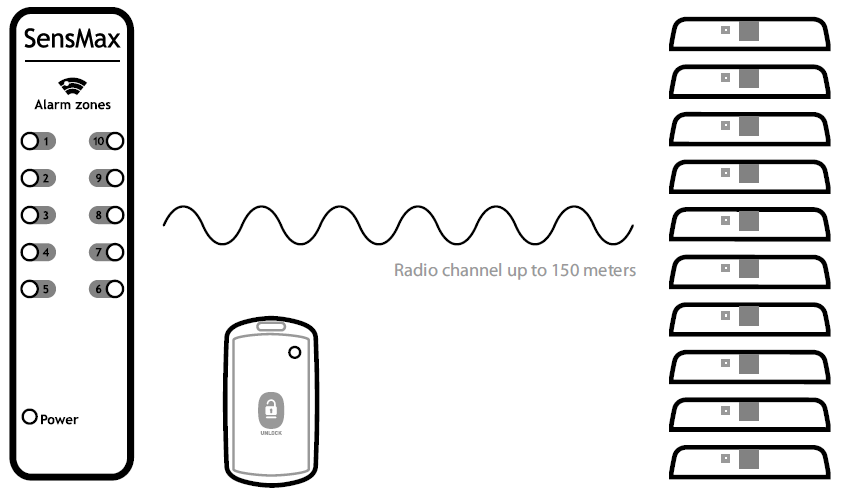
(Radio channel up to 150 meters)
The alarm unit operates on a 5 volt power source (a power unit or computer’s USB port). Audio alarm on the device will be activated after sensor detects a movement in the nearest control zone. Also there will be an indicating light on the panel. It specifies the control zone.
You can plug up to 200 sensors to each alarm unit. The sensors are distributed to 10 control zones. You can plug up to 10 system control key chains to each control zone. The user could adjust several different system control key chains for the work with different control zones, or use one or several system control key chains to unblock all sensors.
If necessary to avoid the alarm action (to open a shop-window), you should press the button of the system control keychain. If necessary to open a few shop-windows, you should press the button of the system control keychain before every opening. After pressing the button user has 10 seconds to open each of controlled shop-windows.
During the unblock time the action of one sensor will activate the alarm, but all other zones will be blocked immediately. If you open more than one shop window, the alarm will be activated immediately.
1. THE SENSOR INSTALLATION
To switch on the sensor, press the JOIN button on the sensor. The red LED will light up for a second, indicating that the sensor is ready for use.
You should start the installation of the SensGuard system placing the sensors on the required objects (doors, shop-window sliding doors). Before attaching the sensor, please make sure, that the sensor position will not interfere door opening.
Also, please make sure, the mobile part is placed from the side of sensitive zone of the sensor. Maximum space between the sensor and the mobile part of the controlled object is up to 30 mm.
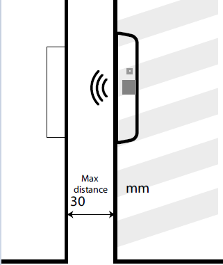
Note: The sensor may detect the movement worse, if objects are optically absorptive or dark. In this case you can attach reflective sticker opposite to the sensitive zone of the sensor.
2. PAIRING OF THE SENSORS AND KEYCHAINS WITH THE ALARM UNIT
In order to ensure the sensors and key chains work only with definite alarm unit, you should execute the equipment binding.
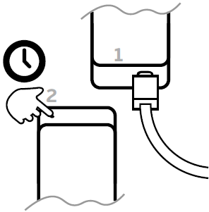
Connect the alarm unit to the power source. Press and hold the MENU button, whereupon the alarm unit will enter the pairing mode.
In the binding mode on the alarm unit is blinking the chosen control zone. In order to choose the control zone you need to bind sensors to, you should press the MENU button.
3. PAIRING SENSORS
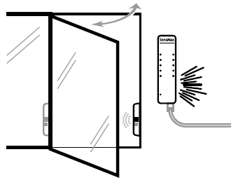
For sensor pairing you should invoke the sensor action (open the shop-window door, where the sensor is installed). The alarm unit should be in pairing mode (point 2).
To bind all of the installed sensors you should open all the doors of the chosen control zone one-by-one. After pairing of the sensor to the chosen control zone is complete, the alarm unit will utter an audio signal. One sensor could be bound only to one control zone of one alarm unit.
4. PAIRING KEYCHAINS
To bind the keychain you should press the button on the keychain. The alarm unit should be in pairing mode (point 2). After pressing the button on the keychain it will be bound to the chosen control zone.
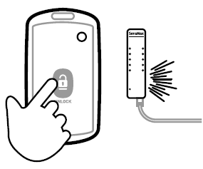
Note: The same keychain could be bound to different control zones. For example, if you need to bind the keychain to all of the control zones, you should switch control zones and press the button on the keychain every time.
5. HOW TO DELETE PAIRINGS
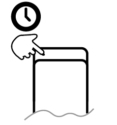
The user can delete all pairings for the chosen control zone. The alarm unit should be in pairing mode (point 2). To delete pairing you should choose the required control zone, then press and hold the MENU button. After few seconds all pairings will be deleted.
6. EXIT THE PAIRING MODE
The pairing mode will be switched off automatically after 60 seconds of standstill. Also, user may switch all 10 control zones, whereupon the alarm unit will exit the pairing mode.
7. SWITCHING ALARM MELODY
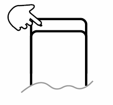
User can change the main melody of the alarm. This melody sounds during the alarm action. To switch a melody you should press the MENU button briefly. The alarm unit should NOT be in pairing mode. Every press activates the next recorded melody.
TECHNICAL SPECIFICATION
| Wireless optical sensor | System control keychain | Alarm unit | |
|---|---|---|---|
| Dimensions | 55x12x27 mm | 65x35x17 mm | 114x36x20 mm |
| Control concept | Optical | - | - |
| Radio signal | 868 MHz | 868 MHz | 868 MHz |
| Range of communication | to 150 m | to 150 m | to 150 m |
| Encryption | AES-128 | AES-128 | AES-128 |
| Control zone | 20-30 mm | - | - |
| Quantity of control zones | 1 | 10 | 10 |
| Quantity of pluggable sensors | - | - | 200 |
| Power supply | Built-in | Built-in | External |
| Operating time | > 5 years | > 5 years | Unlimited |
| Quantity of pluggable units to each control zone | - | - | 10 |