SensMax TAC-B EWP Sensor Configuration: Overhead Mount Mode
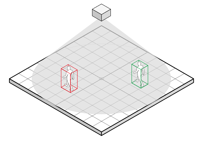
This guide is a logical continuation of the general instruction and overview of the SensMax TAC-B EWP radar sensor and is dedicated to detailed configuration of the parameters of the device installed in overhead mount mode. This mode is recommended for counting visitors in narrow passages or in places where wall mounting is impossible.
This document describes in detail the steps for configuring scene parameters, creating lines and counting zones, as well as network configuration, integration (MQTT, Webhooks), and the notification system.
Home Page: Real-time Monitoring
The Home page (dashboard) is designed for scene visualization and real-time statistics monitoring. It displays user-defined passage lines (Gates) and zones (Zones), as well as real-time trajectories of tracked objects. The summary table presents detailed counting results for each line and zone.
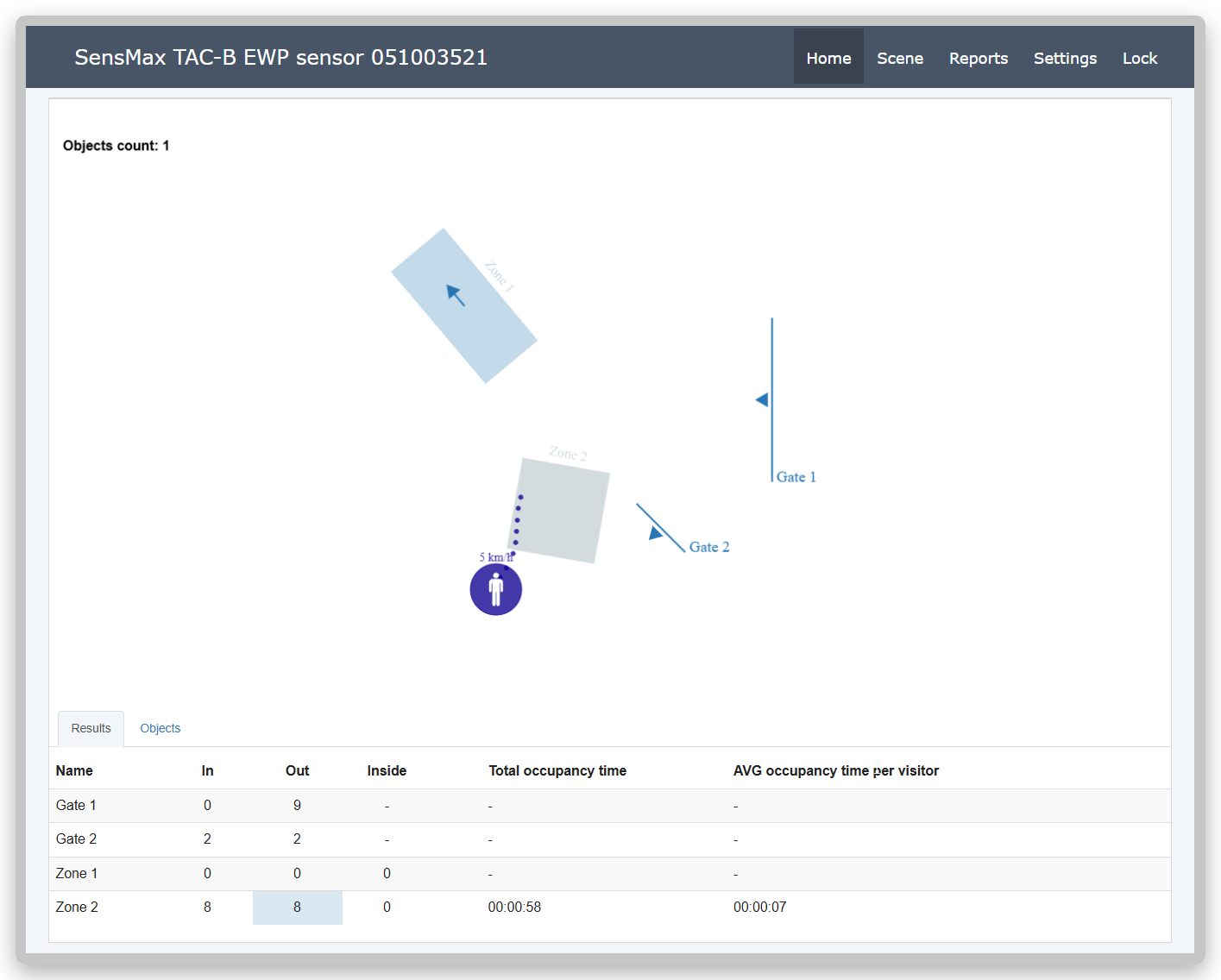
Two tabs are provided for quick access to data:
-
Results - displays overall statistics and counting indicators for the current day for all active lines and zones.
-
Objects - provides information on the last 20 objects detected by the radar.
Counting Logic Setup (Scene)
The Scene section is the main workspace for configuring detection and counting rules. Here you can set virtual lines and zones, limit the active scanning area, as well as configure object filtering (for example, extract counting of pedestrians only or cyclists only) and other parameters. The sensor supports the simultaneous operation of up to 5 counting lines (Gates) and up to 5 zones (Zones).
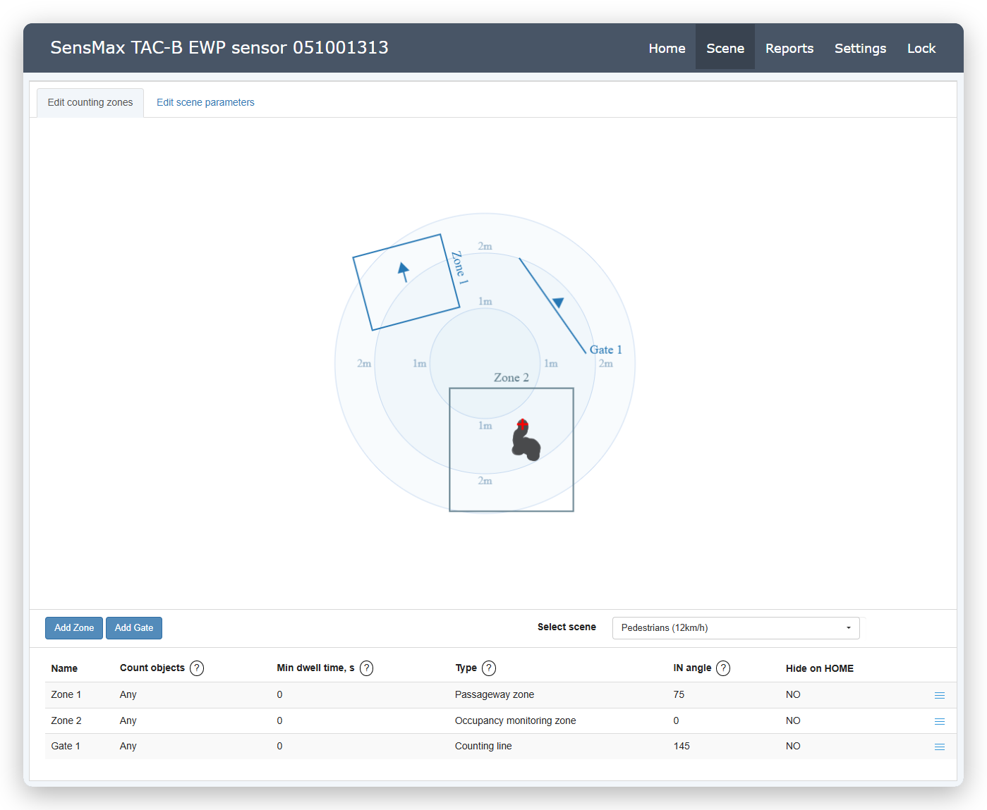
Edit counting zones tab
The Edit counting zones tab is intended for visual markup of the scene. On this tab, you can create new counting zones and lines, determine their type, as well as set general scene parameters.
Select Scene
To ensure maximum counting and object tracking accuracy, it is necessary to select the correct working scene according to the installation conditions. In overhead mode, the sensor offers two main scenes:
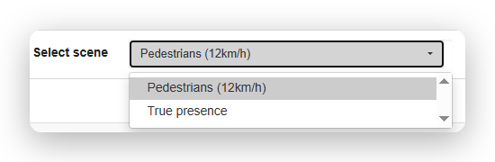
- Pedestrians (12km/h) - a universal option for most standard tasks of counting passing pedestrians.
- True presence - this scene activates special radar sensor algorithms that better track micro-movements. It is designed for cases where static objects (e.g., sitting people) may be in the field of view. Please note that this scene works best in the radar's near zone.
Adding a new counting zone or line
To correctly configure counting zones and lines, you need to determine their exact location on the scene displayed by the radar:
-
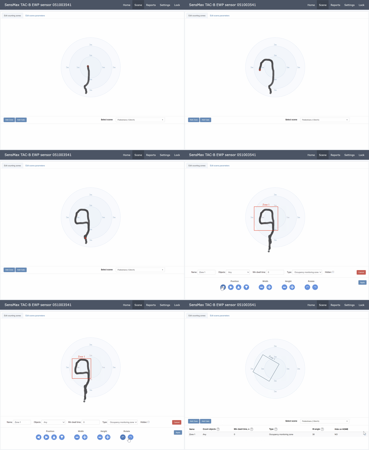
Walk along the perimeter of the actual area where you plan to count. Your route will be displayed in the web interface as a gray trail (movement trajectory).
-
Note: To clear the screen of trails, simply refresh your browser page.
- Click the Add Zone button to create a zone or Add Gate to create a counting line. After that, a new graphic element (zone or line) will appear in the center of the displayed area, and the settings panel will open at the bottom of the screen.
- Focusing on the trail left on the screen, place the graphic zone or line exactly at the actual passage of objects. Use the buttons from the Position section to move the element.
- If necessary, adjust the size and rotation of the element using the Width, Height, Rotate buttons.
Additional settings for a counting zone or line
| Parameter | Description |
|---|---|
| Name | Name of the counting zone or line. |
| Objects | Select the type of objects to track. Options: Any, Adults only, Children only. Note: The object separation function works only when the classifier is enabled in the device's system settings. |
| Type | Zone type: Occupancy monitoring zone or Passageway zone. For more details, see Counting zone types. |
| Hidden | If this option is enabled, the zone or line will be hidden on the Home monitoring page. |
Important
After completing all settings, be sure to click the Apply button at the very bottom of the panel to save the new zone or line.
Edit scene parameters tab
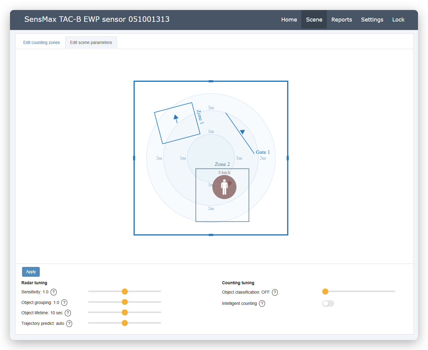
The Edit scene parameters tab is intended for precise adjustment of detection parameters. Here you can adjust the sensor sensitivity, grouping rules for closely walking objects, and set threshold values for the correct classification of pedestrians and cyclists.
Radar Settings
| Parameter | Description |
|---|---|
| Sensitivity | Radar Sensitivity. Determines how easily the sensor picks up movement. Increase the value for better detection of objects at long distances. Decrease if the radar detects "phantom" objects (false reflections from nearby walls and surfaces). |
| Object grouping | Object Grouping (in previous models - Object scaling). Controls the tracker's ability to separate objects moving in a dense group. Decrease the value if the algorithm merges people walking close together into one. Increase if one person is detected as two different objects. |
| Object lifetime | Object Lifetime. Determines how long the algorithm continues to track an object if it has stopped or temporarily disappeared from the field of view. Higher values prevent premature deletion of stopped people (e.g., standing in line). Lower values allow the system to quickly remove random fast objects. |
| Trajectory predict | Trajectory Prediction. Improves counting accuracy at the entrance by restoring the initial path of an object from the moment of its first appearance. Use the Auto mode for automatic calculation based on speed, or set the distance manually if your counting line is located close to a doorway. |
| Object classification height | Object Height Threshold. Sets the threshold value (in centimeters) used by the algorithm to separate passing people into adults and children. Attention: Enabling the object classification function reduces the effective radar field of view. For correct height determination, the object (person) must be entirely within the sensor's field of view cone, which is technically impossible at the very edges of the visibility zone. |
| Intelligent counting | Intelligent Counting. When this function is enabled, the sensor prevents multiple counting of the same object if it crosses the passage line (Gate) or the border of the counting zone several times. |
Important
After changing any parameters on this tab, be sure to click the Apply button for the new settings to take effect.
Active Zone Setup
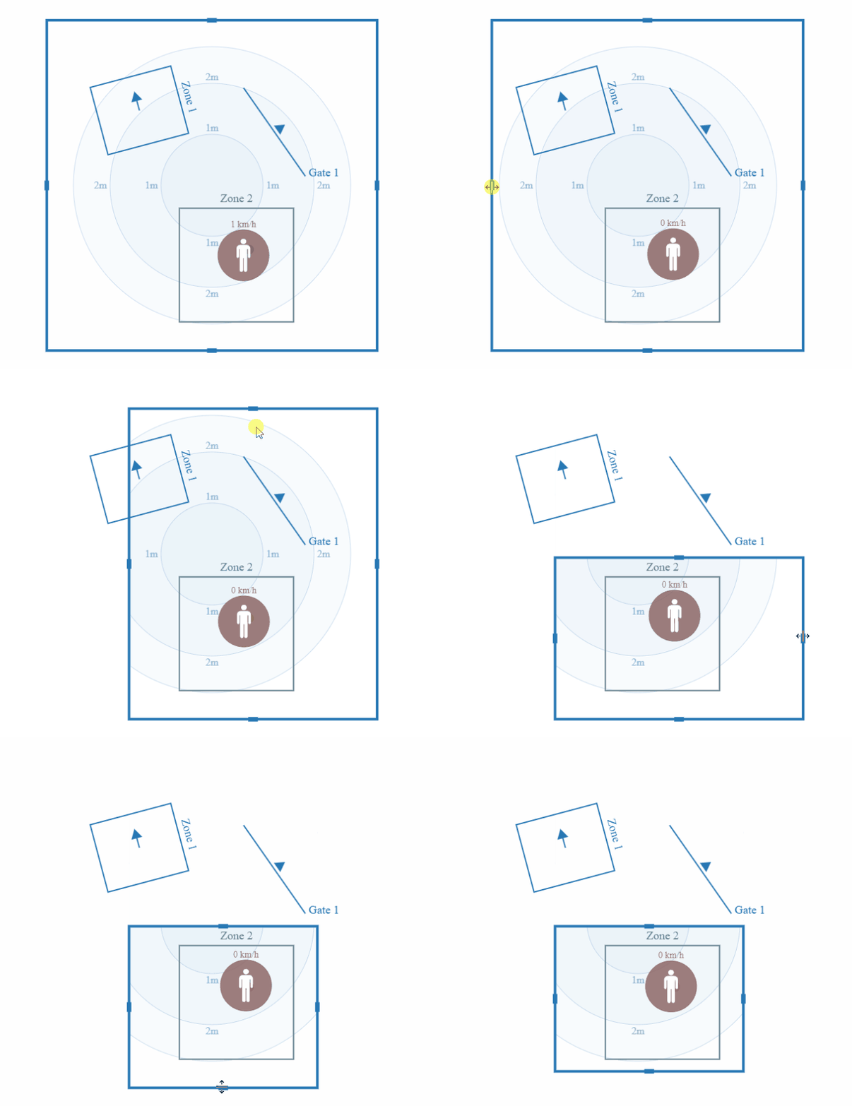
You can limit the radar's field of view by configuring the boundaries of the active scanning area. Objects located inside this area will be detected and tracked by the sensor. Any movements outside the specified boundaries are ignored, which allows you to accurately focus the counting only on the territory you need and ignore extraneous objects (for example, cars on the road or people walking outside the target zone).
General Settings (Settings)
To enter the settings, go to the Settings page in the top menu. The settings are divided into thematic tabs for convenient sensor management.
Mode Tab (Operating Mode)
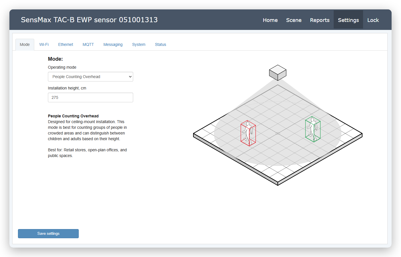
On this tab, the global operating mode of the sensor is selected - wall or overhead. This manual focuses on the overhead operating mode.
-
Operating mode. Make sure People Counting Overhead is selected. This mode is exclusively designed for overhead mounting, where the radar is pointed straight down. It provides accurate visitor counting and is excellent for facilities where wall mounting of the sensor is undesirable or physically impossible.
-
Installation height, cm. Specify the exact actual installation height of the sensor from the floor level (e.g., 275 cm). An accurate value is critically important not only for calculating the overall monitoring area but also for the correct operation of the object classification algorithm by height (separation into adults and children).
Wi-Fi Tab
Wi-Fi is a backup communication channel. The device automatically turns on Wi-Fi if the Ethernet connection is broken or unavailable. The built-in access point (Soft AP) can be used to configure the sensor locally, even if Ethernet is active. This mode remains enabled by default.
Here you can configure the wireless connection to the local network and the parameters of the built-in access point.
-
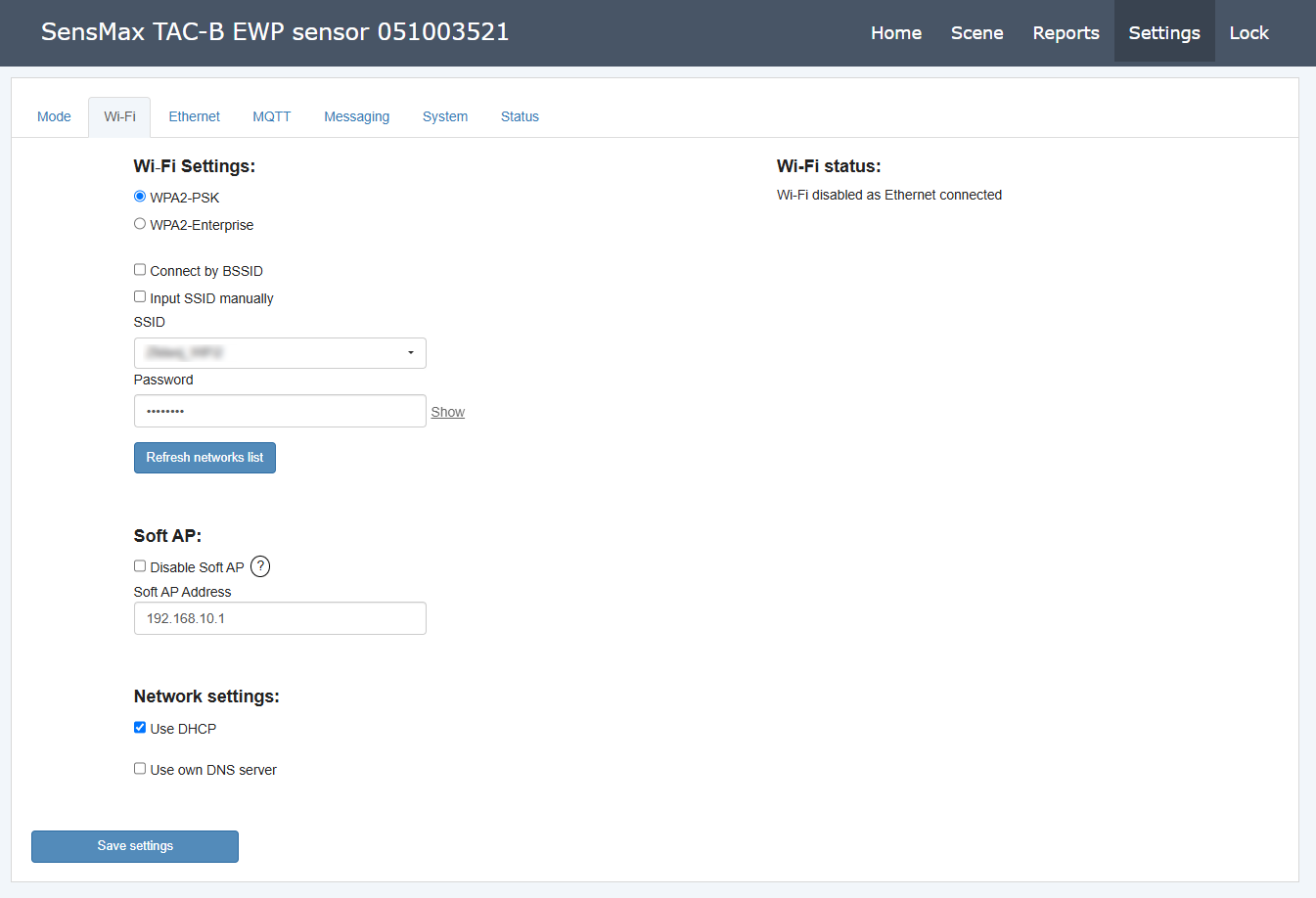
Wi-Fi Settings. In this section, the connection parameters to your network are set. You can choose the WPA2-PSK security protocol (standard password) or WPA2-Enterprise. Options for exact connection by MAC address (Connect by BSSID) or to a hidden network (Input SSID manually) are also available. The network and password are specified in the SSID and Password fields, and the Refresh networks list button updates the list of visible networks.
-
Soft AP (Software Access Point). Managing the sensor's own Wi-Fi network. The Disable Soft AP option allows you to disable this access point (it is recommended to do this for security purposes after setup is complete). The Soft AP Address field allows you to change the IP address of the service access point, which defaults to
192.168.10.1. -
Network settings. The Use DHCP option is enabled by default and is used to automatically obtain network settings from your Wi-Fi router. You can also activate Use own DNS server to manually set your preferred DNS servers.
-
Wi-Fi status. An information panel showing the current state of the wireless module. It may, for example, indicate that Wi-Fi is disabled due to an active Ethernet connection.
Ethernet Tab
Ethernet is the primary communication channel for the sensor. In this section, you configure the wired local area network connection parameters.
-
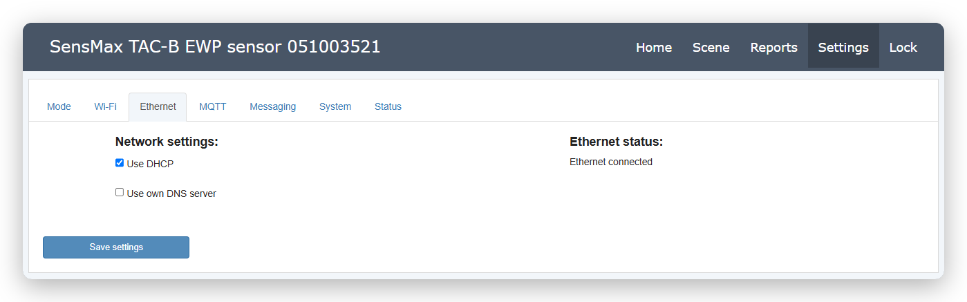
Network settings. The Use DHCP option is enabled by default and allows the sensor to automatically obtain an IP address from the router. If you need to manually configure DNS addresses, you can activate the Use own DNS server option.
-
Ethernet status. An information panel confirming the presence of physical and logical connection. Upon successful connection, the status is displayed here, for example, Ethernet connected.
MQTT Tab
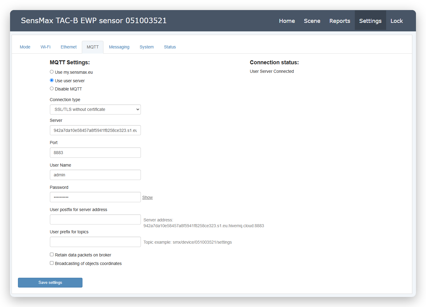
This tab allows you to configure the MQTT connection. The user can select one of the MQTT brokers: the SensMax cloud (my.sensmax.eu) or a custom broker (Use user server). You can also completely disable sending data via MQTT (Disable MQTT).
-
Use my.sensmax.eu (SensMax Cloud). To configure the device to work with the proprietary system, you must select this option.
-
Use user server (Custom Server). This option allows you to manually configure the settings of your MQTT broker. In the Connection type field, select the appropriate option: Credentials, SSL/TLS, Two-way auth, Mutual auth, WebSocket, or WebSocket Secure. Next, specify your broker address in the Server field and the port for connection in the Port field.
-
User prefix for topics. Optionally, the user can add any prefix to the topic name. The maximum length is 128 characters. An example of the resulting topic is displayed to the right of the field.
-
User postfix for server address. Optionally, the user can add any postfix to the server address. The maximum length is 128 characters. An example of the generated address is displayed on the right.
-
Retain data packets on broker. If enabled, data packets will be retained on the MQTT broker. For more information, refer to the MQTT documentation.
-
Broadcasting of coordinates. If enabled, the sensor will send a special packet with the coordinates of all currently detected objects. A Short packet contains only the current object coordinates. A Long packet contains the current coordinates as well as a history of the 10 previous positions.
Detailed description of the protocol, topic structure, and transmitted data formats is available in a separate documentation: MQTT Specification.
Messaging Tab
The radar sensor supports integration with Email and Telegram services for automated sending of system notifications and statistical reports. Basic setup of connection parameters to these platforms is performed on this tab. After successful configuration and communication check, you will be able to select Email or Telegram as target delivery channels when creating your own notifications and report schedules.
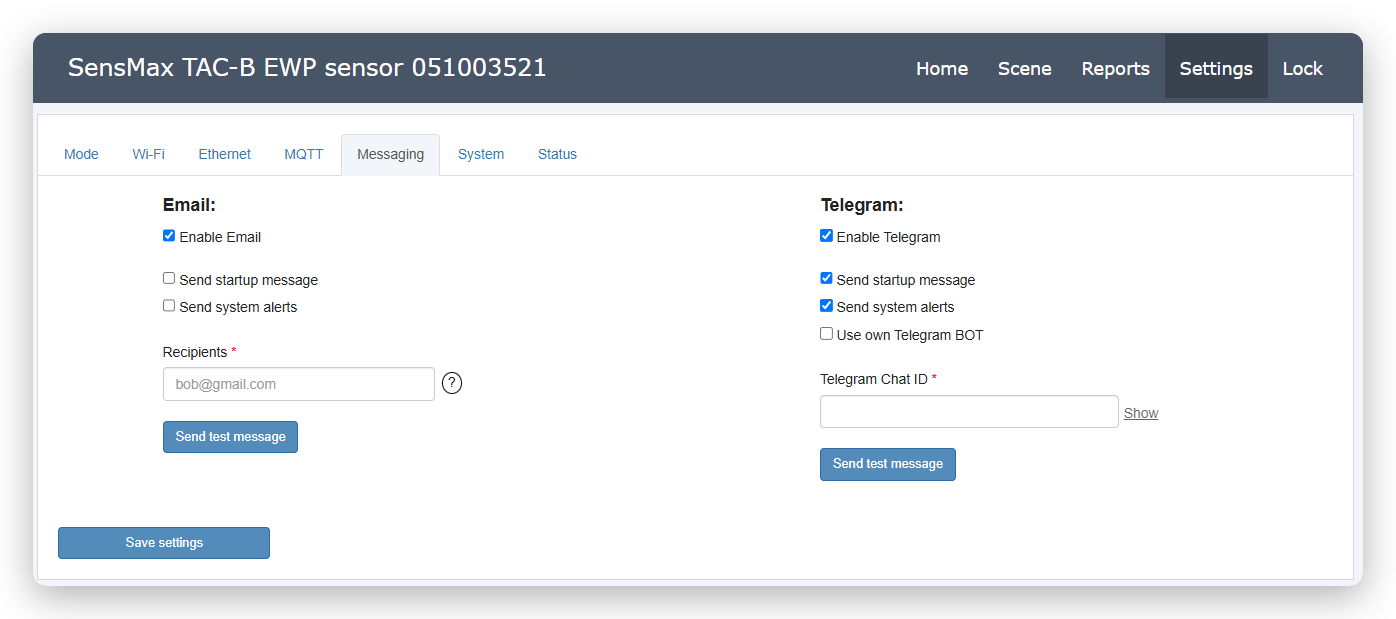
The Enable Email option enables integration with email services. This communication channel is often used to receive regular statistical reports and notifications. You can choose which system messages the sensor will send automatically:
- Notifications about device startup or reboot (Send startup message).
- Important system alerts (Send system alerts).
The Recipients field specifies recipient addresses (you can specify up to three addresses separated by commas). After filling in the data, be sure to use the Send test message button to send a test email and ensure the settings are correct.
Telegram
The Enable Telegram option enables sending notifications directly to the Telegram messenger, providing instant delivery of important alerts. Similar to email, you can configure the automatic sending of startup messages (Send startup message) and system alerts (Send system alerts) here.
For notifications to work, you need to link the sensor to your chat via a unique Telegram Chat ID. There are two ways to connect: through the official SensMax service bot or through your own bot.
Method 1: Using the official SensMax bot (default)
This is the easiest and fastest way to start receiving notifications.
- Open the Telegram app.
- In the main menu, select New Channel.
- Come up with a name, click Create and select the channel type (private or public).
- At the stage of adding participants, enter
sensmax_botin the search bar and select the official SensMax BOT (@sensmax_bot). - The system will warn you that bots can only be added as administrators. Confirm the action by clicking Make admin.
- Immediately after adding, a message containing your Chat ID will appear in the chat window (usually starts with a minus, e.g.:
-1001600...).
Copy the received identifier and paste it into the Telegram Chat ID field in the sensor settings.
Method 2: Use own Telegram BOT
Activate the Use own Telegram BOT option if you want to use your own corporate bot. Detailed instructions on creating and configuring your own bot are described in a separate guide. After configuring the bot, you need to get the identifier of your chat or channel and paste it into the Telegram Chat ID field in the sensor's web interface.
Connection Check
After selecting either method and filling in the settings, be sure to use the Send test message button to send a test message and verify the connection with Telegram servers.
System Tab
Global device configuration is carried out on this tab, including system time management, social distancing functions, as well as security and interface appearance settings.
Time and Date Settings
The sensor supports the NTP time protocol. By selecting the Automatic NTP time option, the device will automatically receive accurate time from the internet (by default via the pool.ntp.org server). You can also set the time manually using the Set time and date manually option. In the Time Zone and Use daylight saving time fields, your time zone and automatic transition to daylight saving/winter time are set.
Note: The sensor has a built-in non-volatile clock that continues to keep time for several hours even when the device is completely powered off.
Social distance settings
Here you can configure parameters for recording social distance violations. The sensor continuously measures the distance between closely located objects. If this distance is less than the set value (Minimal allowed distance between objects, in cm) and is maintained for longer than the specified time (Delay, in sec) when the permissible number of objects (Allowed objects count) is exceeded, the sensor generates a notification. Social distance monitoring is performed for all user zones.
More settings
Device parameters not included in the main categories are collected in this block:
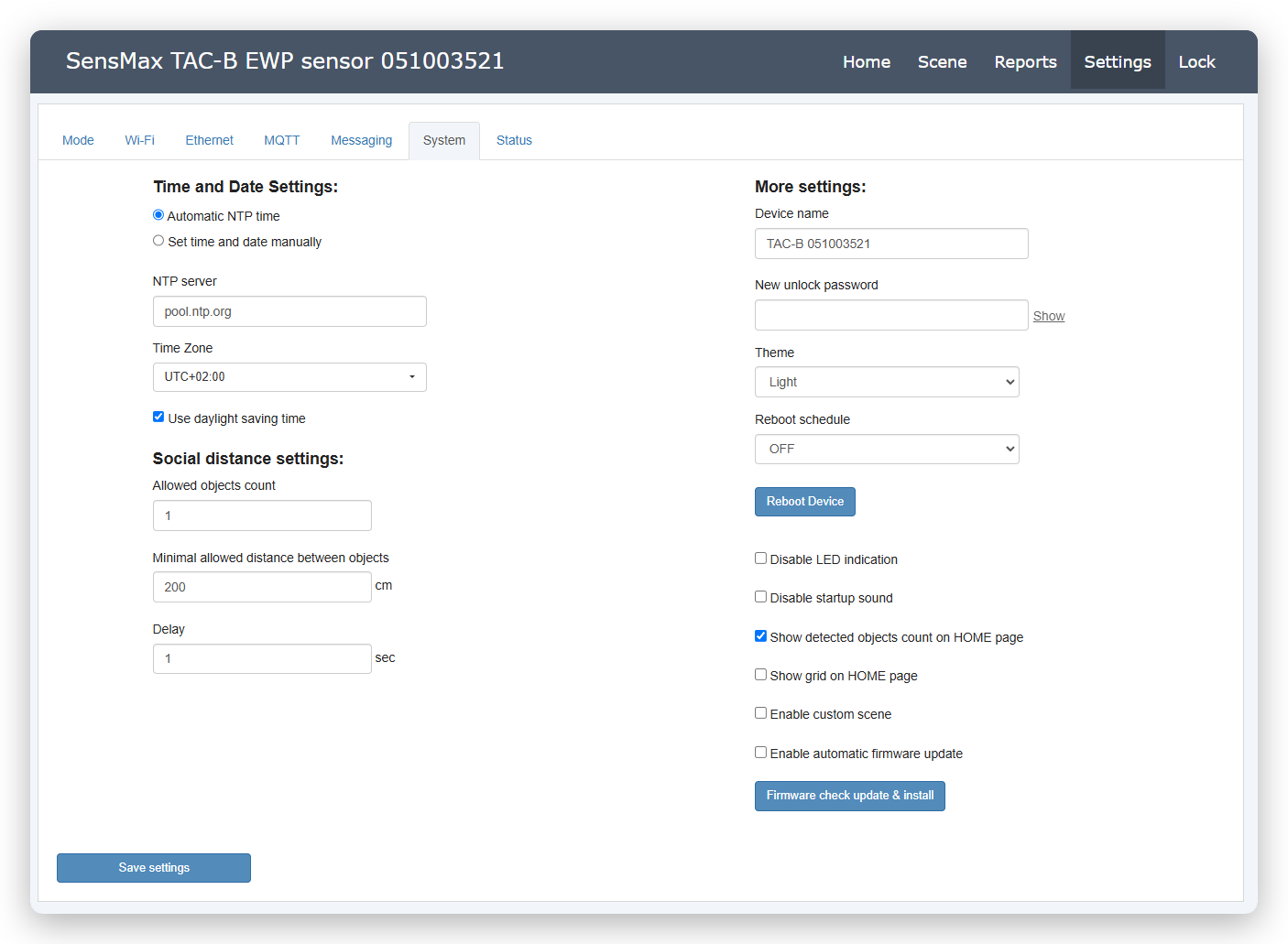
- Device name. A user-friendly name for identifying the sensor in the reporting system.
- New unlock password. Here you can change the password used for both the device access point (Soft AP) and the settings page. We strongly recommend changing the password if you are still using the default factory password.
- Theme. Selection of the web interface color scheme (e.g., Light theme).
- Reboot schedule. Setting up a schedule for preventive reboot of the sensor (e.g., daily at night). Use the Reboot Device button for immediate reboot.
- Disable LED indication. If this parameter is selected, all LED indication on the sensor will be disabled.
- Disable startup sound. If this parameter is selected, the welcome melody will not be played upon device startup.
- Show detected objects count. If enabled, the detected objects counter will be displayed on the main page.
- Show grid on HOME page. If this parameter is selected, the sensor field of view grid will be displayed on the main page.
- Enable custom scene. Activation of a custom radar scene.
- Enable automatic firmware update. If enabled, the device will check for firmware updates at random intervals (from 2 to 8 hours). If a new firmware is found, it will be installed automatically, after which the device will reboot. If the option is disabled, you must manually check for updates using the Firmware check update & install button.
Status Tab
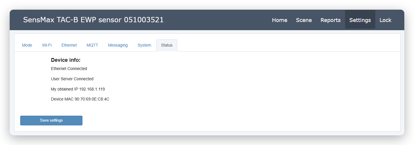
A summary information dashboard displaying the current status of the device and its network interfaces.
-
Device info. Here you can see the status of key system components:
-
Network connection status (e.g., Ethernet Connected or Wi-Fi Connected).
- MQTT broker connection status (e.g., User Server Connected).
- My obtained IP - the current local IP address of the sensor assigned by your router.
- Device MAC - the physical MAC address of the device (may be required to assign a static IP address on the router).
Attention
After making changes on any of the configuration tabs, be sure to click the Save settings button (in the lower left corner of the screen) for the new settings to take effect.
Reports
To navigate to the report settings, open the Settings page in the main menu of the web interface. This section allows you to create, configure, and manage regular statistical reports, as well as system notifications. The report configuration interface consists of three tabs: Today Report, CSV Report, Notifications
Data Fields
Before proceeding with the creation of reports, familiarize yourself with the available metrics. Depending on the type of configured zone (passage line or occupancy zone), you can include the following data in the report:
- Incoming - the number of objects that crossed the line or entered the zone in the forward direction.
- Outgoing - the number of objects that crossed the line or left the zone in the backward direction.
- Visitors - the number of unique visitors. Calculated using the formula:
- For passage lines and transit zones:
VISITORS = (INPUT + OUTPUT) / 2 - For occupancy zones:
VISITORS = INPUT - Passages - the total number of crossings. Calculated using the formula:
- For passage lines and transit zones:
PASSAGES = INPUT + OUTPUT - For occupancy zones:
PASSAGES = INPUT - AVG Occupancy Time - the average time objects spend in the zone. Available only for occupancy monitoring zones.
- Total Occupancy Time - the total time spent by all objects in the zone. Available only for occupancy monitoring zones.
- First / Final Visit Time - the time of the first and last recorded event for the selected period.
Today Report Tab
On this tab, statistical data collected by the sensor for the current day is generated and displayed.
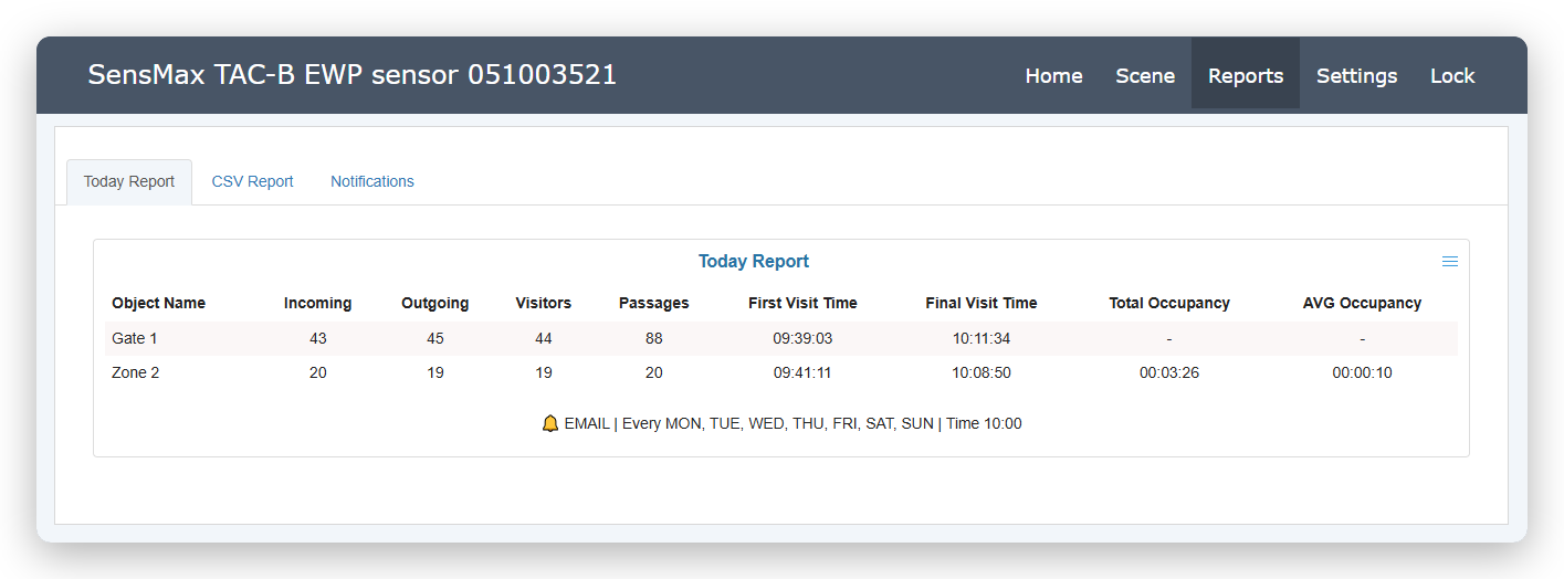
To create a new report, click the Create report button and fill in the following parameters:
- NAME - specify a user-friendly name for your report.
- REPORT STYLE - select a display style (e.g., TABLE VIEW for tabular view).
- SELECT ZONE - check the boxes for counting lines and zones whose data should be included in the report.
- DATA FIELDS - select the necessary metrics (Incoming, Outgoing, Visitors, Passages, time of first/final visits, and occupancy time).
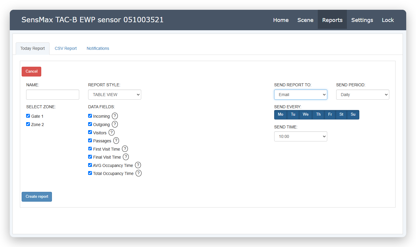
Automatic Sending Configuration: You can set up automatic mailing of this report to Email or Telegram (delivery channels must be pre-configured in the Settings -> Messaging section).
- In the SEND REPORT TO field, select the target communication channel.
- Set the period and regularity in the SEND PERIOD (e.g., Daily) and SEND EVERY (select days of the week) fields.
- Specify the exact dispatch time in the SEND TIME field.
After saving the settings, the generated report will appear on the page. At the bottom of the table, service information about the configured sending schedule will be displayed.
CSV Report Tab
Here regular reports are configured, which are automatically written to the built-in Micro SD card in CSV format. You can create up to 20 different reports. Reports can be manually downloaded directly from the page or configured for scheduled automatic sending via Email or Telegram.
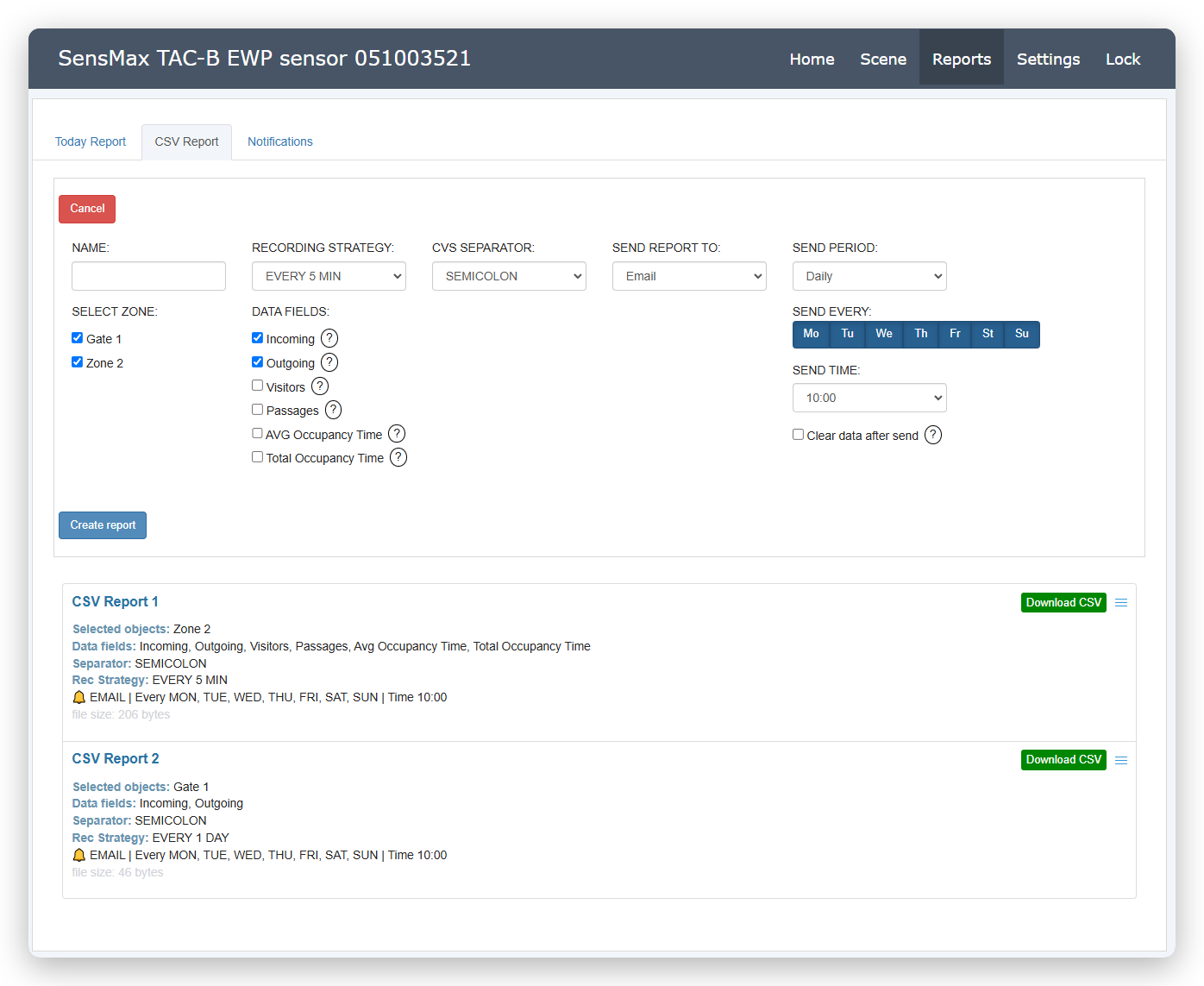
To create a new report, click the Create report button and fill in the following parameters:
- NAME - specify a user-friendly name for your report.
- SELECT ZONE - check the boxes for counting lines and zones whose data should be included in the report.
- RECORDING STRATEGY - select the frequency of recording data to the file (EVERY 5 MIN, EVERY 1 HOUR, EVERY 1 DAY, or EVERY MOTION - recording upon every movement).
- CVS SEPARATOR - select the delimiter for the CSV file (SEMICOLON, COMMA, TAB).
- DATA FIELDS - select the necessary metrics (Incoming, Outgoing, Visitors, Passages, time of first/final visits, and occupancy time).
Automatic Sending Configuration: You can automate the export of CSV files by setting up regular sending:
- In the SEND REPORT TO field, choose the sending channel (Email, Telegram) or disable automatic sending (DO NOT SEND).
- Set the period and regularity of mailing in the SEND PERIOD (e.g., Daily) and SEND EVERY (select days of the week) fields.
- Specify the exact dispatch time in the SEND TIME field.
- Clear data after send - if this option is selected, after a report is successfully sent via email or Telegram, the data on the Micro SD card will be cleared. This allows you to start recording with a clean slate, so that the next sent file contains data only for the new reporting period, and not for the entire history of observations.
Notifications Tab
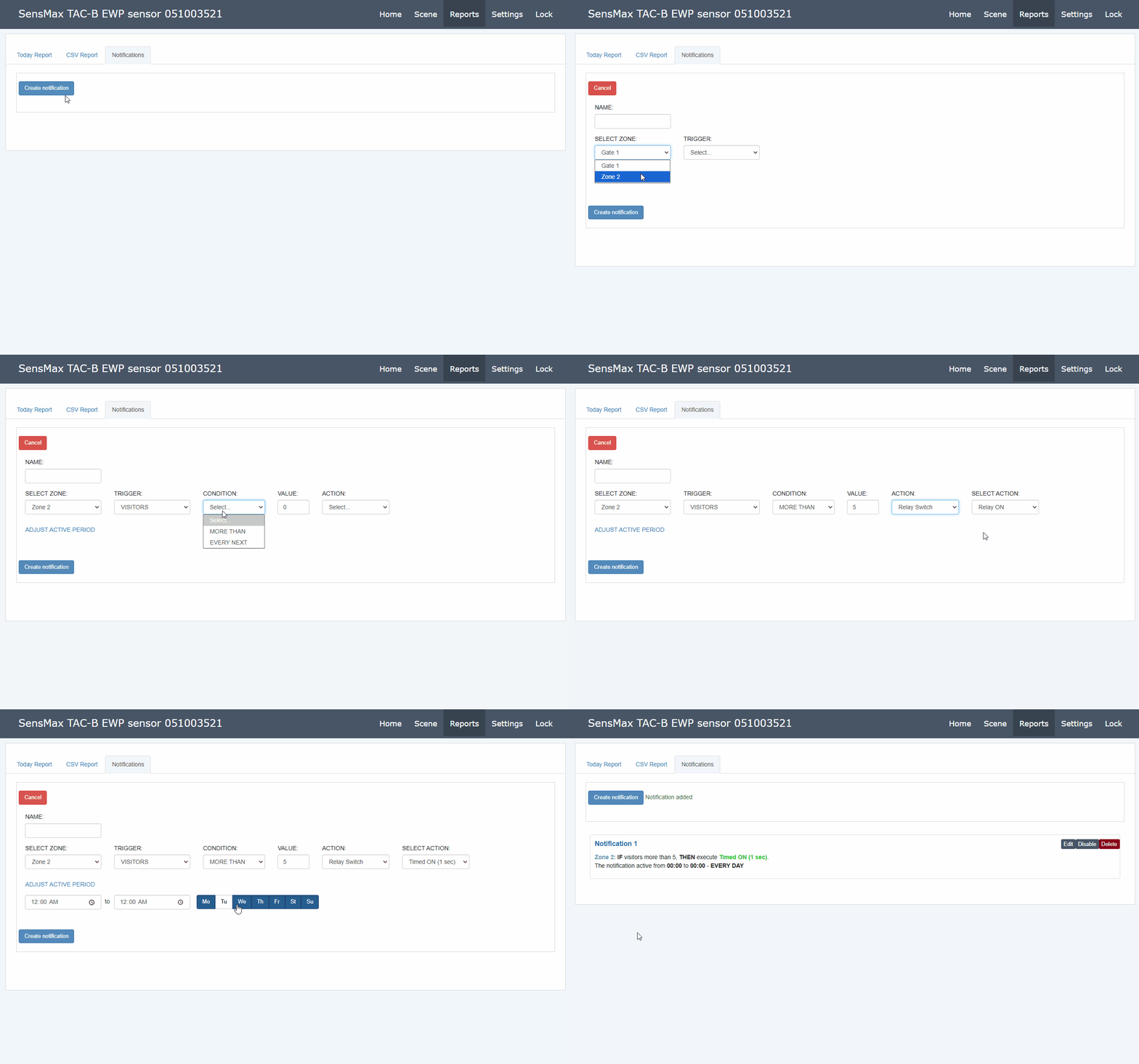
On this tab, you can set up automatic notifications (alerts) about various events recorded by the sensor. You can create up to 20 different notifications.
To create a new notification, click the Create button and set the following parameters:
- OBJECT - select the object (passage line or zone) for which the notification is being configured.
- TRIGGER - select the event that will cause it to trigger. The list of available triggers depends on the selected object type:
- For passage lines (Gate): INCOMING, OUTGOING, VISITORS, PASSAGES, ANY MOTION, FIRST VISITOR, EVERY 5 MIN, EVERY HOUR.
- For zones (Zone): additionally available are INSIDE ZONE (current number of objects inside), ZONE IS EMPTY, SOCIAL DISTANCE VIOLATION, and TOTAL OCCUPANCY TIME.
- CONDITION - select the condition type:
- MORE THAN - the sensor will generate a one-time notification when the value exceeds a specified threshold.
- EVERY NEXT - a notification will be generated every time the value increases by a specified step.
- VALUE - specify a numerical value to trigger the condition.
- DELAY - (parameter available only for the INSIDE ZONE trigger) specify the delay time. The condition must be maintained continuously for this time before a notification is sent.
- ACTION - choose the action that will occur upon triggering:
- Email notification - sending an email.
- Telegram notification - sending a message to the Telegram messenger.
- MQTT notification - sending a message to the MQTT broker.
- Webhook launch - triggering a webhook (HTTP request).
- Relay Switch - switching the built-in relay (for details, see the relay configuration guide).
- Sound Alert - playing a sound alert through the sensor's built-in speaker.
Webhooks Support
The sensor supports triggering webhooks for integration with popular IoT platforms and automation services (e.g., IFTTT or Shelly). This allows the sensor to directly send control commands to other smart devices (for example, turn on lights, start ventilation) or transfer data to third-party systems.
To set up integration:
- Select Webhook launch in the ACTION field when creating a notification.
- In the field that appears, provide the webhook URL generated by your automation service.
What's Next?
- Return to the general device overview: SensMax TAC-B EWP: Overview and specifications
- If you need to configure the sensor for wall mounting, proceed to the manual: SensMax TAC-B EWP: Configuration (Wall)