Technical Specification
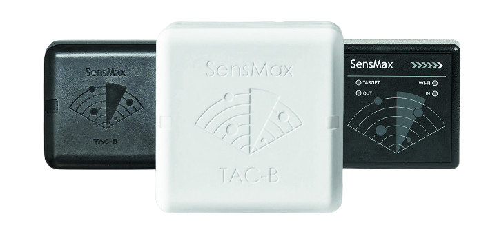
TAC-B W/WP/4G SERIES RADAR SENSORS
Description
The SensMax TAC-B sensors use the mmWave contactless technology which operates in the spectrum 60 GHz. The sensor emits a scanning “chirp” and receives reflections from objects.
SensMax TAC-B sensors can be used for robust indoor/outdoor sensing in all lighting, smoke, fog, rain, detect very fine motions, penetration through materials like plastic, fabric, and drywall. Using of original SensMax software is optional, but sensor can be used without it.
The SensMax TAC-B sensors supports popular IoT MQTT protocol, Email and Telegram API. These features gives reach opportunities for integration of TAC-B sensor to any projects.
Key features include:
-
4D Real-time Tracking: Tracks moving objects in four dimensions: X, Y, Z coordinates, and speed.
-
Object Counting: Counts moving objects within user-defined counting lines and zones
-
Privacy Compliant: Collects anonymous data, ensuring 100% GDPR and privacy law compatibility.
-
Object Differentiation: Distinguishes between different types of moving objects, such as pedestrians and cyclists, based on their speed.
-
Simple Installation: Easy to install on a wall at a height of 2-3 meters.
-
Offline Operation: Can work offline by storing data on a built-in Micro SD card and uploading it to the server once a network connection is restored.
-
Intelligent Counting: Prevents double-counting of objects.
-
Flexible Notification & Reporting: Integrated with Email, Telegram & MQTT.
Application
The TAC-B sensors can be used for:
-
people counting in different gates and zones
-
outdoor people counting
-
occupancy monitoring
-
dwell time measurement
-
social distance violation detection
-
building automation
-
smart city projects
-
security projects
Model comparison
| Model | IP rating | Application | Dimensions, mm |
Wi-Fi connection |
Low-power features |
4G LTE modem |
Color |
|---|---|---|---|---|---|---|---|
| SensMax TAC-B 3D-W |
IP54 | Indoor | 80×80×35 | + | — | — | Black |
| SensMax TAC-B 3D-WP |
IP65 | Indoor / Outdoor | 80×80×45 | + | + | — | Black |
| SensMax TAC-B 4G |
IP65 | Indoor / Outdoor | 120×120×45 | + | + | + | White |
Technical specification
| Enclosure | Polycarbonate plastic IP65 |
|---|---|
| Counting accuracy | For range 10m >99% (for density 1 persons per m2) |
| Field of view | 120° horizontal, 60° vertical |
| Max range | Pedestrian / cyclists detection: 10 m Car detection: 20m (available for outdoor models only) |
| Range resolution | 5cm for 5 m scene / 10 cm for 10 m scene / 20 cm for 20 m scene |
| Max speed of object | 50 km/h |
| GDPR privacy law | 100% compliant (provides complete anonymity) |
| Notifications & Reporting | Onboard Email and Telegram notifications and reports. MQTT support. |
| Internet connection | Wi-Fi 2.4 GHz / WPA2-PSK / WPA2-ENTERPRISE (PEAP-MSCHAP v2) 4G LTE (for TAC-B 4G only) |
| Data storage | SD card 8 GB (enough for storage of >100 year of counting data with 5 minutes step) |
| Power | 12VDC 0.5A (AVG power consumption is 4 WH in active mode) |
| Low-power mode consumption |
Available for outdoor models only. Low power scanning mode enabled: 2 WH Low power network mode enabled: 3.2 WH Low power scanning mode & Low power network mode enabled: 1.2 WH Suspend mode: 0.2 WH |
| Working temperature | –25...+65°C |
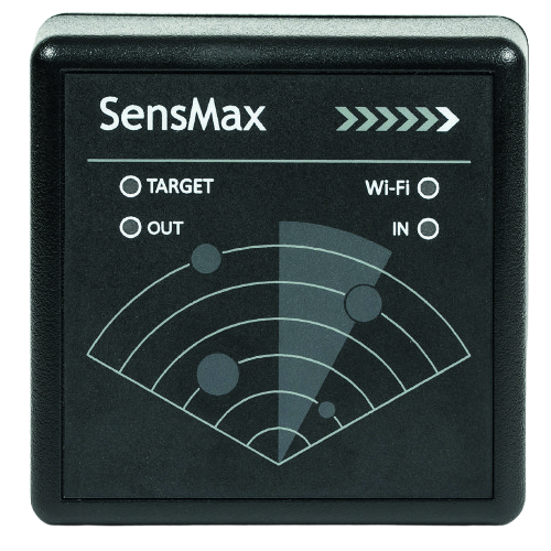
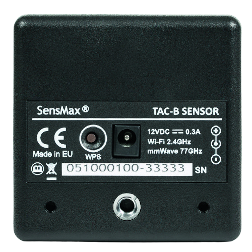
TAC-B 3D-W sensor elements
| Icon | Status | Description |
|---|---|---|
| [1] TARGET LED (YELLOW) | Blinking | Sensor captured at least one target. The blinking frequency is dependent from distance from object till sensor (fast blinking for near target and slow for the far target). |
| [2] Wi-Fi LED (GREEN) | Lights | Wi-Fi Network & server both connected. |
| Flashes 1 time per sec | Wi-Fi connected but server not connected. | |
| [3] OUT LED (RED) | Flashes | Blinks when sensor detects new OUTGOING visitor for any Gate or Zone. |
| [4] IN LED (RED) | Flashes | Blinks when sensor detects new INCOMING visitor for any Gate or Zone. |
| [5] Button | Short Press | No action. |
| Press and hold 30 sec | Apply Factory Reset. | |
| [6] Power supply | n/a | Standard 5 mm diametre power supply connector. |
| [7] Mounting hole type A | n/a | Hole for fixing of standard SensMax bracket. |
| [8] Mounting hole type B | n/a | Standard tripod 1/4-20 UNC thread. |
| [9] Serial number | n/a | Device serial number. |
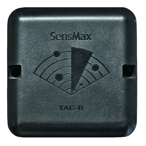
TAC-B 3D-WP sensor elements
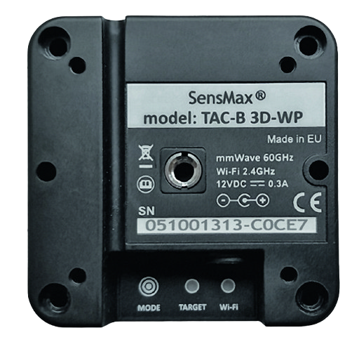
| Icon | Status | Description |
|---|---|---|
| [1] TARGET LED (YELLOW) | Blinking | Sensor captured at least one target. The blinking frequency is dependent from distance from object till sensor (fast blinking for near target and slow for the far target). |
| [2] Wi-Fi LED (GREEN) | Lights | Wi-Fi Network & server both connected. |
| Flashes 1 time per sec | Wi-Fi connected but server not connected. | |
| [3] Button | Short Press | Wake up from suspend power mode (if enabled). |
| Press and hold 30 sec | Apply Factory Reset. | |
| [4] Power supply | n/a | Standard 5 mm diametre power supply connector. |
| [5] Mounting hole type A | n/a | Hole for fixing of standard SensMax bracket. |
| [6] Mounting hole type B | n/a | Standard tripod 1/4-20 UNC thread. |
| [7] Mounting hole type C | n/a | Through hole for mounting the sensor on the wall. |
| [8] Serial number | n/a | Device serial number. |
TAC-B 4G sensor elements
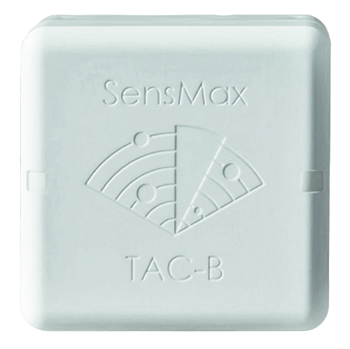
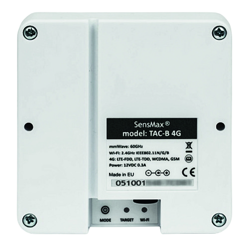
| Icon | Status | Description |
|---|---|---|
| [1] TARGET LED (YELLOW) | Blinking | Sensor captured at least one target. The blinking frequency is dependent from distance from object till sensor (fast blinking for near target and slow for the far target). |
| [2] Wi-Fi LED (GREEN) | Lights | Wi-Fi Network & server both connected. |
| Flashes 1 time per sec | Wi-Fi connected but server not connected. | |
| [3] Button | Short Press | Wake up from suspend power mode (if enabled). |
| Press and hold 30 sec | Apply Factory Reset. | |
| [4] Power supply | n/a | Standard 5 mm diametre power supply connector. |
| [5] Mounting hole type C | n/a | Through hole for mounting the sensor on the wall. |
| [6] Serial number | n/a | Device serial number. |
TAC-B 4G sensor SIM card installation
The SensMax TAC-B 4G sensor is equipped with a built-in 4G router for mobile internet connectivity. To use it, please install a SIM card following the instructions below.
SIM Card Preparation:
-
Ensure you have a Micro-SIM card with an active data plan.
-
Important: The PIN code check must be disabled on the SIM card before installation.
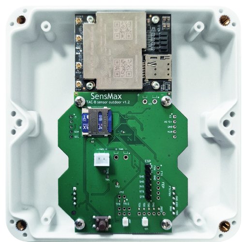
SIM card installation process:
- Open the Enclosure: Carefully unscrew
SIM Micro
the four screws on the sensor’s case.
- Be Careful: While removing the cover, hold
it steady to avoid damaging the internal power cable.
- Install the SIM Card: Insert your Micro-SIM
card into the dedicated slot until it clicks into place.
- Reassemble the Sensor: Close the enclosure
and securely fasten the screws.
4G Router Configuration & Access
-
Connecting to the Router: The 4G router creates its own Wi-Fi access point with a name (SSID) like Wireless_BXXXXX. The default Wi-Fi password is the same as the sensor’s serial number (for example: 051001313).
-
Advanced Settings: If you need to configure the APN or other specific 4G router settings, connect to its access point using a mobile phone or laptop. Then, open a web browser and navigate to 192.168.100.1 to access the configuration page.
TAC-B sensor Installation
-
Recommended installation height is higher than 2 meters above the floor.
-
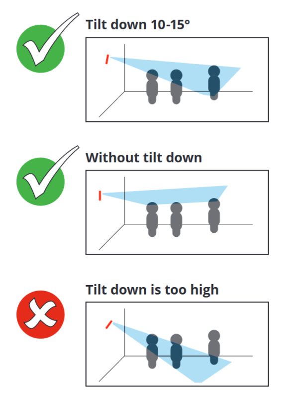
The sensor beam should be directed above the heads.
-
If the installation height is more than 2.5 meters, a slight tilt down of 10-15 degrees is recommended. This improves the detection of far objects.
-
Don’t increase the tilt too much, this will cause the near object will obscure the far object.
Optimal installation height: 2.5-3.5 m
Down tilt (optionally): 5-10 degrees
Configuration of sensor using web page
All configurations are available on the device web page.
To access settings web page, please do following steps:
-
Connect device to power supply.
-
Scan for available Wi-Fi networks on your Laptop or Mobil Phone.
-
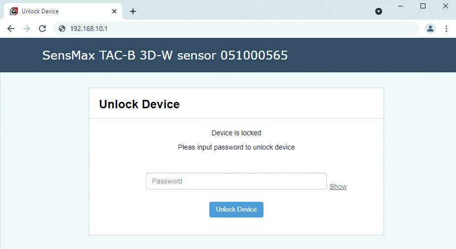
Connect to TAC-B Access Point (AP name is “SensMax TAC-B XXXXXXXXX”). The default password is same as device Serial Number. For example, in this document the device AP will be SensMax TAC-B 051000565, and password will be 051000565.
-
Open your web browser.
-
Input IP address 192.168.10.1 to address bar and press Enter.
The login page will be opened. To unlock settings, please input your password again (for this example, password is 051000565).
Home web page
The Home page shows user defined gates and zone, how also currently tracked objects. The table below shows detailed counting result for every gate and every zone.
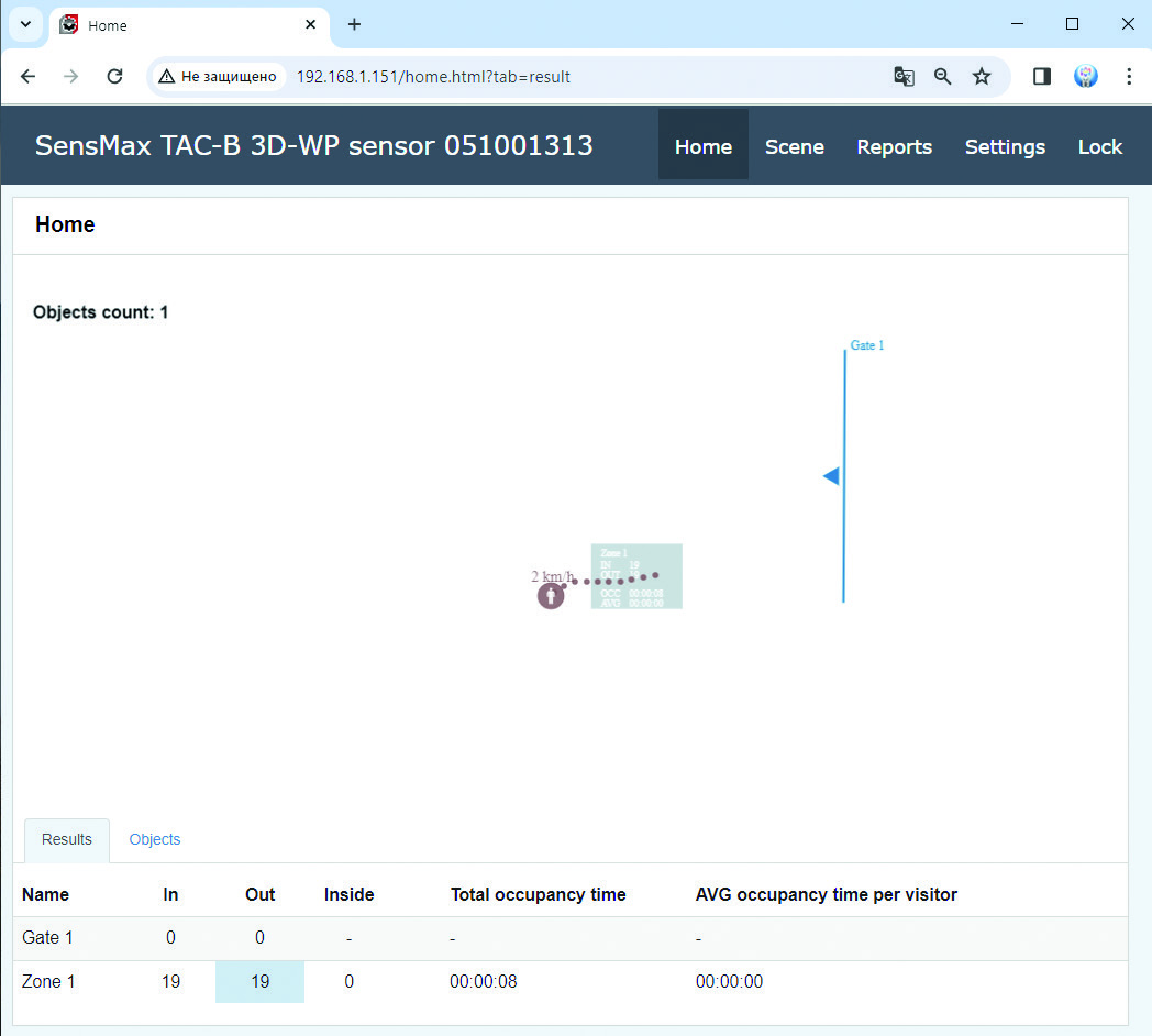
The Results tab displays today’s counts for all lines and zones.
The Objects tab displays information about the last 20 detected objects.
Scene web page
To enter page please press Scene tab.
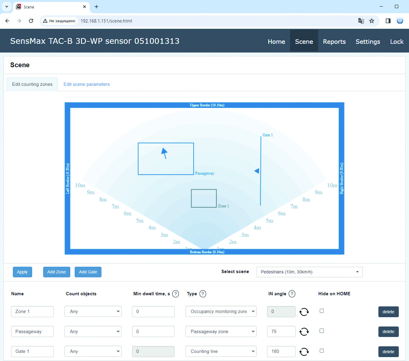
The Scene page allows to setup scene parameters, user defined counting lines, zones and other parameters.
User can add up to 5 Gates and up to 5 Zones.
Counting options
For each Gate or Zone it is possible to set different options to adjust counting preferences.
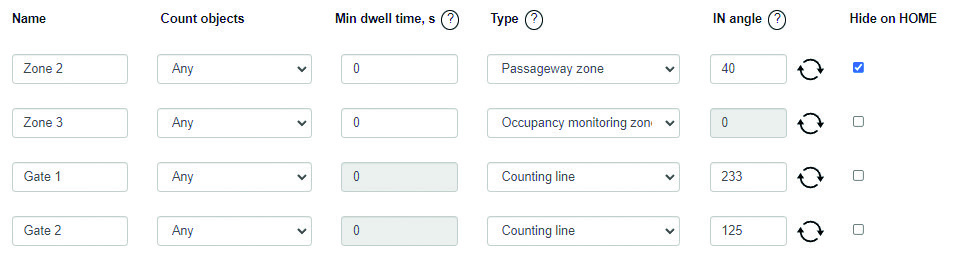
| Name | The name of Gate or Zone. Max lenght is 16 symbols. |
|---|---|
| Count objects | Allows to select the type of objects to be counted for current Gate or Zone: Any, Pedestrians or Vehicles. |
| Min dwell time | The Min dwell time is a time which object must spend inside the Zone in order to be counted. If Min dwell time set to 0, each object will be counted immediately when it visits Zone. |
| Type | This setting allows to set the type of current Gate or Zone. For Gates is only available the Counting line type. For Zones user can select Occupancy monitoring zone or Passageway zone type. Please refer to Page 15 of current document for more information about types. |
| IN angle | This setting allows to adjust the direction of INCOMING flow. |
| Hide on HOME | This setting allows to hide corresponding Gate or Zone on Home page. |
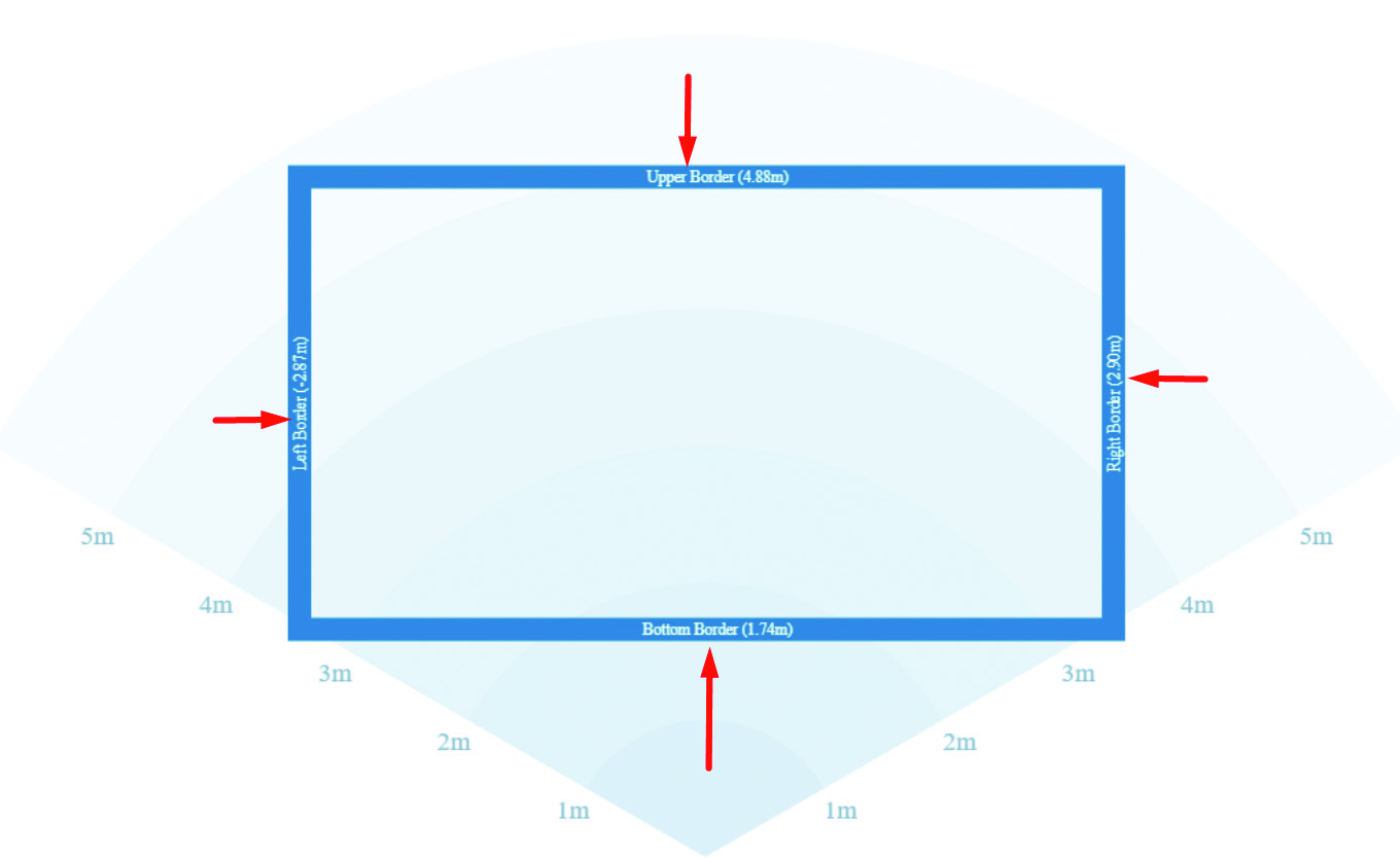
Walls
User can configure the active area by moving the borders.
Targets inside active area will be detected and tracked, targets outside of this area are ignored.
Select scene
To provide best counting and tracking results it is important to select scene correctly. User can select one from pre-defined scenes.
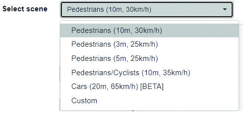
Please note: The range resolution is different for different scenes. The better resolution provides more accurate separation of objects. The 5 m scene has 5 cm resolution. The 10 m scene has 10 cm resolution.
Edit scene
User can adjust main parameters for any scene by entering to Edit scene parameters tab.
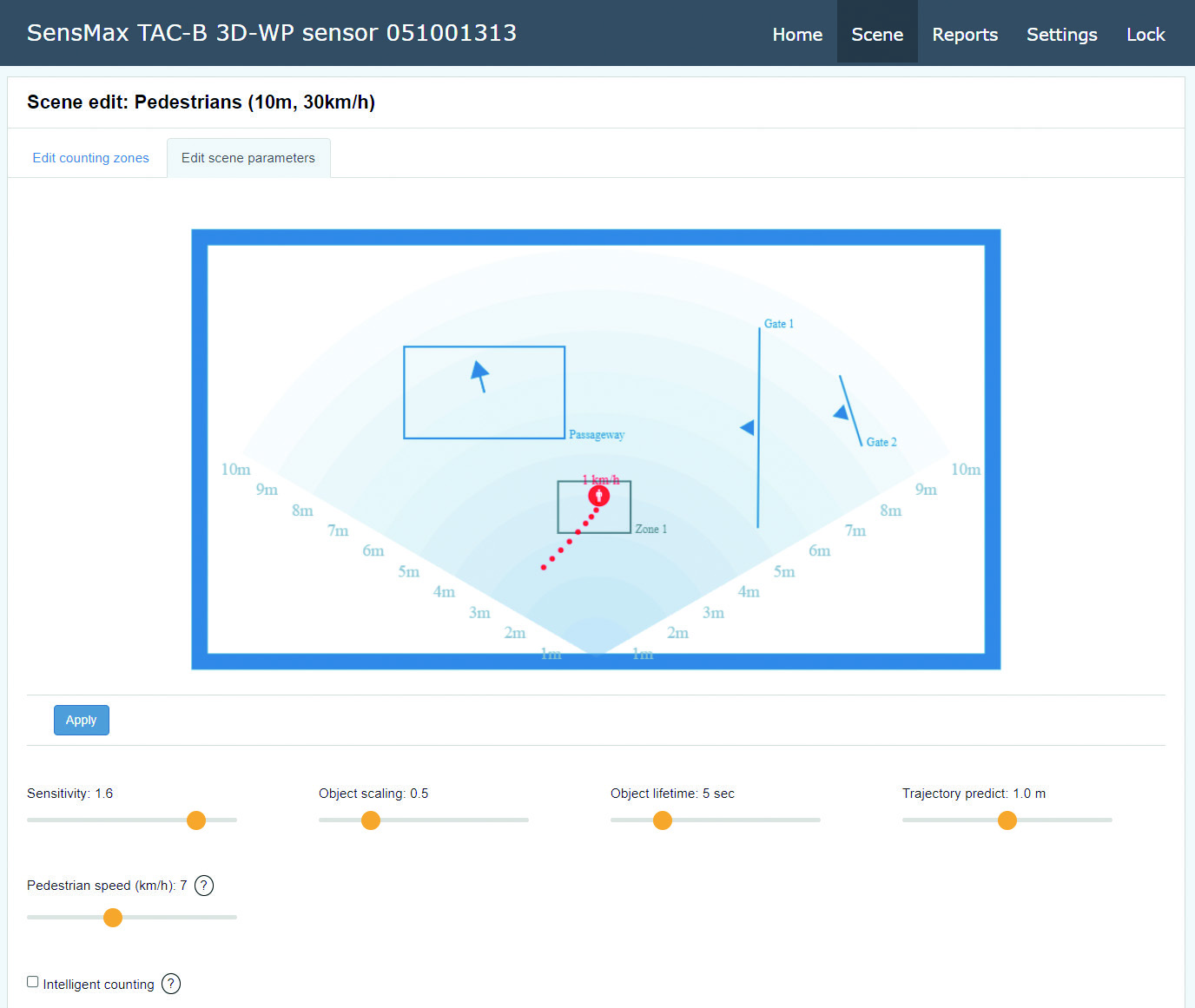
| Pedestrian speed | This setting defines the max speed of pedestrians. If speed of object is below this value, the object will be marked as “pedestrian”. If object faster than it will be marked as “vehicle”. |
|---|---|
| Sensitivity | This setting allows to adjust sensitivity of sensor. Higher value allows to recognize any fine movement for outdoor use. For indoor use, sometimes the tracker is detecting too many people in the scene (ghosts). One likely cause is multipath reflections (radar Energy reflected from a person being reflected again from a wall, ceiling, floor or some object). In this case it may be necessary to reduce sensor sensitivity to remove ghosts. |
| Object scaling | This setting allows to adjust the reference object volume. When people are near each other and walking at the same pace in the same direction, there is needed some reference object size for the tracker for recognize all objects correctly. If sensor recognize few people as single track, please decrease this value. And if sensor recognize single people as multiple tracks, please increase this value. |
| Object lifetime | This setting defines the lifetime of static objects. The object becomes static when there is no any motion detected. It is recommended to use low values (1…10 sec) if your main target to count passing people. For projects where main purpose is occupancy monitoring of defined zones, it may be necessary to use higher values. |
| Trajectory predict | Sometimes situations arise where the sensor may lose a tracked object. For example, an object has left the room and thus disappeared from the radar’s field of view. The algorithm analyses the speed and direction of the object and predicts its movement by some distance. This significantly improves the counting accuracy for such complex scenarios. |
| Intelligent counting | If smart counting is enabled, the sensor counts an object once and skips the count if the object crosses the gate or zone repeatedly. |
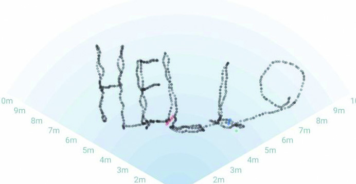
Route line
For convenient adjustment of the sensor, the movement of the objects are displayed on the field of view. Routes are not erased, so you can accurately position the counting zones based on the image of the routes.
Gates
The Gate (or counting line) indicates doors or entrances.
Each Gate has an IN and OUT direction.
The arrow located on the line of passage indicates the IN direction.
To add a Gate, click the Add Gate button and do two mouse clicks, at the start point and at the end point of Gate.
The Gate can only have a Counting line type - count moving objects which are crossing specified line in defined direction.
Zones
Counting zones are indicated as rectangles.
Each Zone has the INSIDE parameter, which displays the number of people inside the Zone at the moment. Also for Zones it is possible to measure dwell time and social distance violation.
Each zone can have a Occupancy monitoring zone type or Passageway zone type.
The Occupancy monitoring zone works following:
When object come in into Zone, it counted as IN and when object leave Zone it counted as OUT. All visitors entering to Zone will be counted with the direction IN, and all those who leave Zone will be counted with the direction OUT.
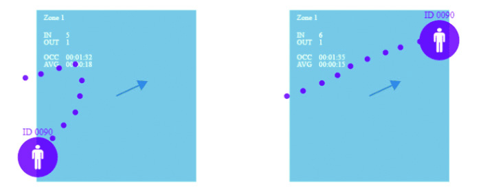
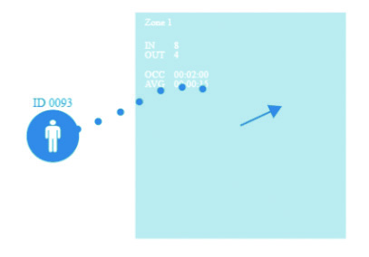
The Passageway zone works following:
When the sensor detects an object crossing the Zone, the algorithm analyses the direction in which the object is moving and, depending on the direction of movement, counts IN or OUT. Independent from which point in Zone an object starts its movement, the algorithm will analyse object’s trajectory and decide in which direction the object is moving.
In case if an object has entered to Zone, turned around, and left Zone in the same direction, such object will be ignored by the counting algorithm.
Object filtered out
Object counted
Object counted
Creating of user gates or zones
To add a counting gate or zone, click the Add Zone button, and with two clicks, mark the beginning and end of the zone.
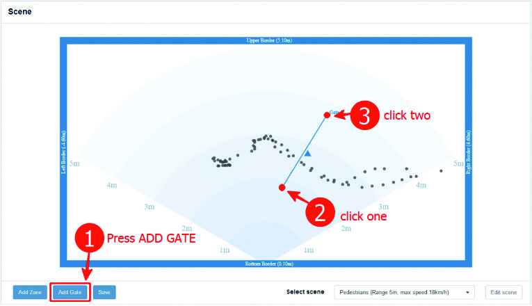
Example of adding of new Gate:
- Go several times along the route where the gate should be marked. Your route will be draw on field of view (grey dotted line on picture below).
-
Press Add Gate button.
-
Click in desired place to indicate the beginning of gate.
-
Click again to indicate the end of gate.
-
Press Save button.
Do the same steps for adding of Zone.
Settings web page
To enter page please press the Settings tab in upper menu. All settings are divided into tabs.
Network
This tab contains network settings.
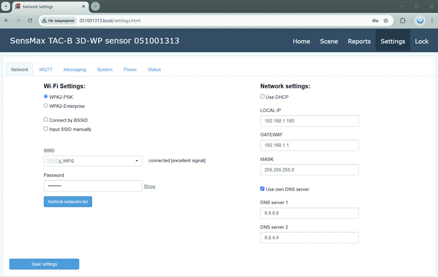
Wi-Fi Settings
To connect to new Wi-Fi network, please press the Refresh networks list button.
After few seconds, all founded networks will be displayed in SSID list. Please choose the correct Wi-Fi network and input password.
To connect to hidden Wi-Fi network, please set Input SSID manually flag and input desired SSID and password manually.
Network settings
If Use DHCP is selected, all network settings will be obtained from internet router automatically (the DHCP should be enabled in your internet router). Or you can input all network settings manually.
If Use own DNS server is selected, you can set your own DNS servers. By default, Google’s DNS servers 8.8.8.8 and 8.8.4.4 are used.
MQTT
This tab allows to configure the MQTT connection.
The user can select one of the MQTT brokers: the SensMax cloud (my.sensmax.eu) or the user broker.
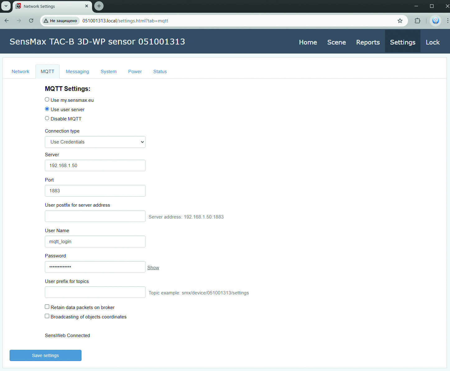
MQTT Settings
To setup device for working with my.sensmax.eu system, the Use my.sensmax.eu setting should be used.
To setup own MQTT broker, please use one from possible settings: Credentials, SSL/TLS, Two-way auth, Mutual auth, WebSocket, WebSocket Secure.
| User prefix for topics | Optionally, user can add any prefix to topic name. Max lenght is 128 symbols. |
|---|---|
| Retain data packets on broker | If enabled, the data packets will be stored on MQTT broker. Please refer to MQTT documentation for more info. |
| Broadcasting of coordinates | If enabled, sensor will send the special packet which contains coordinates of all currently detected object. The Short packet represent current positions of objects only. The Long packet represent current positions of objects, how also history of 10 previous positions. |
| User postfix for server address | Optionally, user can add any postfix to server address. Max lenght is 128 symbols. |
Messaging
The TAC-B sensor can send notifications and reports to Email and Telegram.
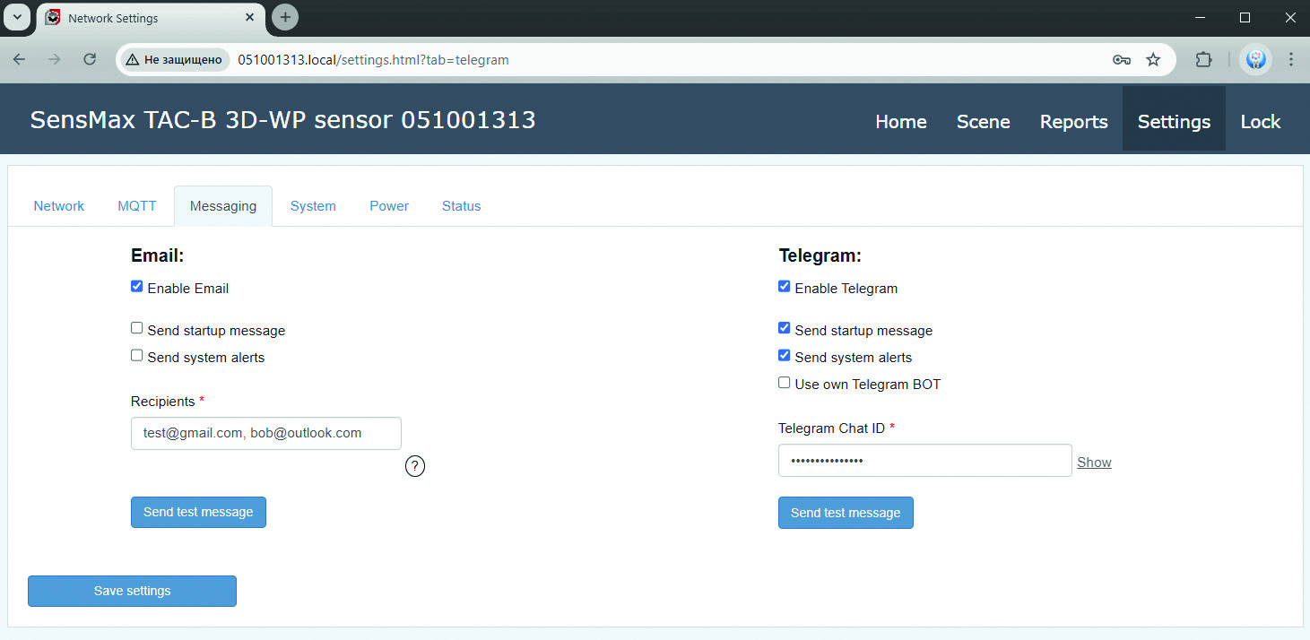
To enable Email, please select the Enable Email option and specify up to three recipients, separating them with commas.
In addition to custom notifications and reports, the user can enable a startup message and system notifications, such as the start of a firmware update.
Telegram
To enable Telegram, please select the Enable Telegram option.
Telegram messenger sends messages using bots. You can use the SensMax bot, or you can create your own bot.
Connection of SensMax BOT:
-
Open your Telegram app
-
Press the menu button , and select the New Channel.
-
Enter channel name and press the Create button.
-
Select type of new channel (Private or Public).
-
In next step Telegram will ask you to add members into your channel. Please typo sensmax_bot in search field and select the SensMax BOT:

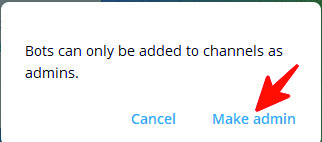
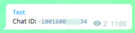
- When everything done, you will see the Chat ID in Telegram chat window. Please input your Chat ID to the TAC-B sensor.
Connection of user BOT
System
On this tab user can configure various settings.
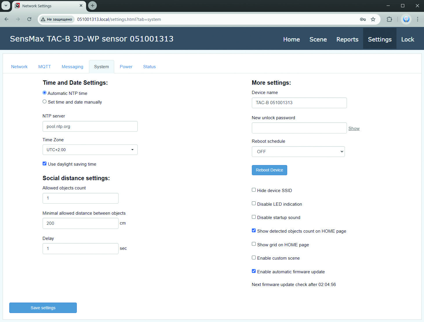
Time and Date Settings
The TAC-B sensor supports the NTP time protocol. If Automatic NTP Time option selected, device will get internet time automatically.
Also it is possible to set time and date manually.
The sensor has a built-in non-volatile clock that continue working during few hours even if the sensor power is turned off.
Social distance settings
Here you can adjust parameters for social distance violation.
The sensor measures the distance between nearby objects, and if this distance is less than the determined value and persists for longer than the specified time, the sensor generates a notification.
Social distance monitoring is performed for all user zones.
Please refer to Notification section of this manual for getting more information about notifications.
More settings
| PASSWORD | Here you can change password which used for collector AP and settings page both. We recommend to change password if you still use default password. |
|---|---|
| Hide device SSID | If this setting selected, you cannot connect to device directly using of connection to collector AP. But if collector already connected to your local network, you able login to settings web page from any PC inside this network. To do this, you will need to input the collector IP address in internet browser. |
| Disable LED Indication | If selected, all LED indication will be disabled. |
| Disable startup sound | If selected, the greeting melody will not be played when device startup. |
| Show borders in HOME page | If selected, the borders of active area will be shown on home page. |
| Show grid on HOME page | If selected, the field of sensor view will be shown on home page. |
| Enable automatic firmware update |
If enabled, device will check firmware updates in random period of time 2…8 hours. If new firmware found, it will be installed automatically. Device will reboot after update. If disabled, user can check firmware update manually. |
Power
This tab is only available for outdoor devices (TAC-B 3D-WP and TAC-B 4G).
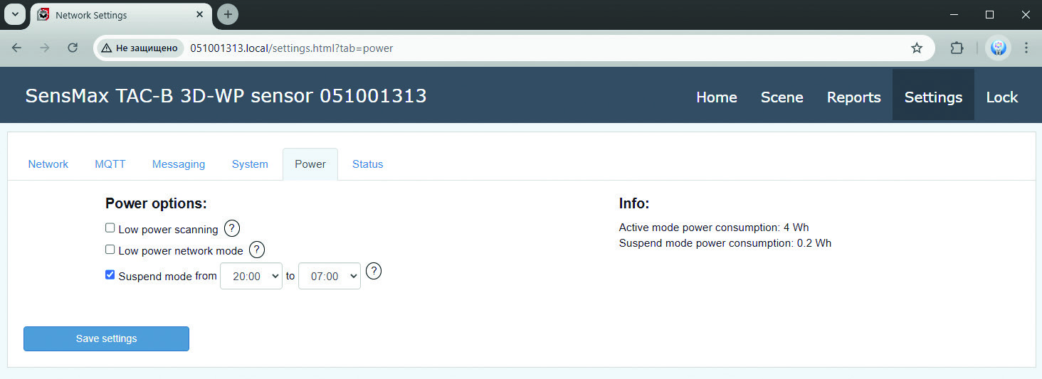
This tab allows the user to configure various power-saving settings to optimize energy consumption.
Low power scanning
If this mode is enabled, the radar will send several scanning pulses per second to detect any movement in the scene. If motion is detected, normal scanning mode is activated. When the scene remains empty for more than 10 seconds, the low power scanning mode will turn on automatically.
This mode allows for an average energy saving of up to 2 Wh.
However, in a scenario where fast-moving objects such as cyclists or cars are possible, this mode is not recommended, as fast objects may not be detected when it is in use.
Low power network mode
If this mode is enabled, Wi-Fi (and the 4G LTE MODEM for the TAC-B 4G model) will turn on every hour to send accumulated data and reports. In this mode, the sensor will not send instant notifications or MQTT packets of the single_ts type. This mode saves an average of 0.8 Wh of energy.
To access the sensor’s access point, Wi-Fi must be forcibly enabled. The user can do this by pressing the sensor’s button or by power cycling the sensor. After activation, the Wi-Fi (and the 4G LTE MODEM on the TAC-B 4G model) will remain active for five minutes.
Suspend mode
The user can configure a time-based schedule to enable Suspend mode.
When this mode is active, the sensor is in its lowest power consumption mode. Scene scanning, object tracking and object counting are disabled. Wi-Fi and the 4G LTE MODEM are disabled. In this mode, the sensor consumes 0.2 WH of energy.
To forcibly wake the sensor from Suspend mode, you must press the sensor’s button or simply power cycle the sensor. After a reboot, the sensor remains on for five minutes.
Status
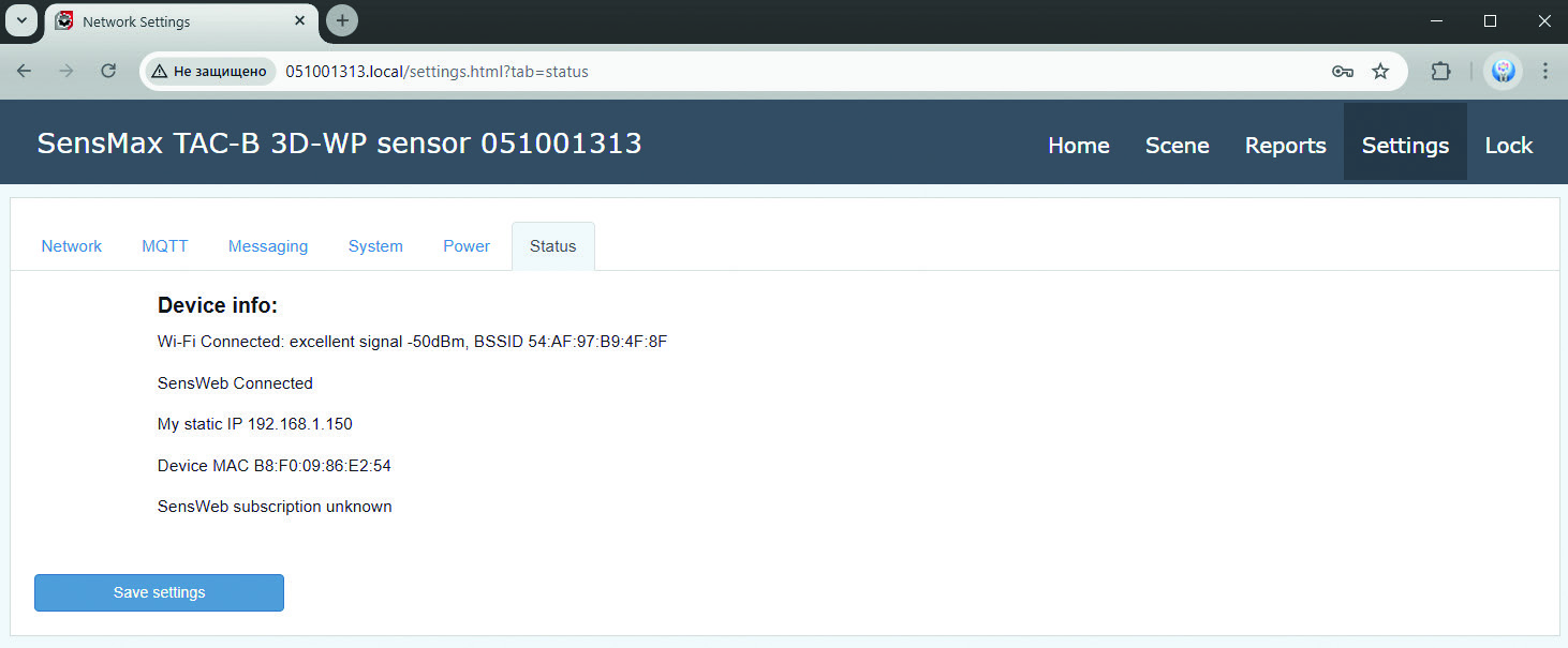
On this tab actual system status shown.
Reports web page
To enter page please press the Reports tab in upper menu. This page contains allows to manage Reports and Notifications.
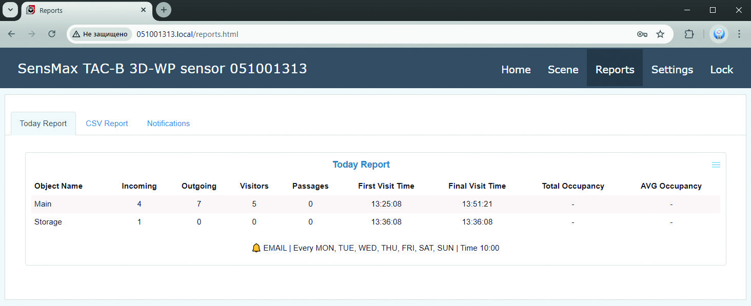
Today Report
This type of report allows user to view information for today in the form of a table or a list.
The user can configure automatic sending of the report to Email or Telegram.
For creating of new report, please press the Create button and setup desired parameters.
CSV Report
On this tab user can configure CSV reports.
The user can configure automatic sending of the report to Email or Telegram.
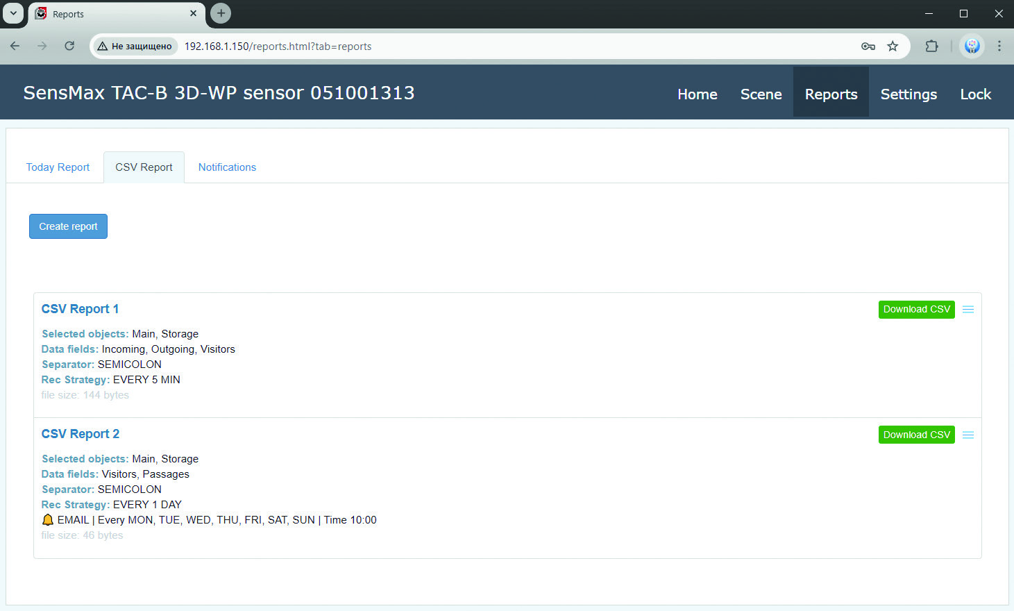
For creating of new report, please press the Create button and setup desired parameters:
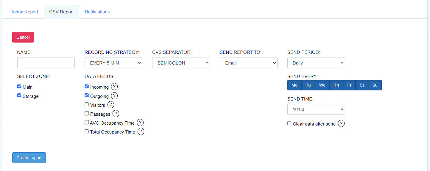
Once the report has been created, the sensor begins writing the data to a CSV file on the built-in Micro SD card. To download the report, press the Download CSV button of the desired report.
Please note:
-
The VISITORS field calculated by formula: For Gates and Passageway Zones: VISITORS = (INPUT + OUTPUT)/2 For Zones: VISITORS = INPUT
-
The PASSAGES field calculated by formula: For Gates and Passageway Zones: VISITORS = INPUT + OUTPUT For Zones: VISITORS = INPUT
Notifications
On this tab user can configure notifications.
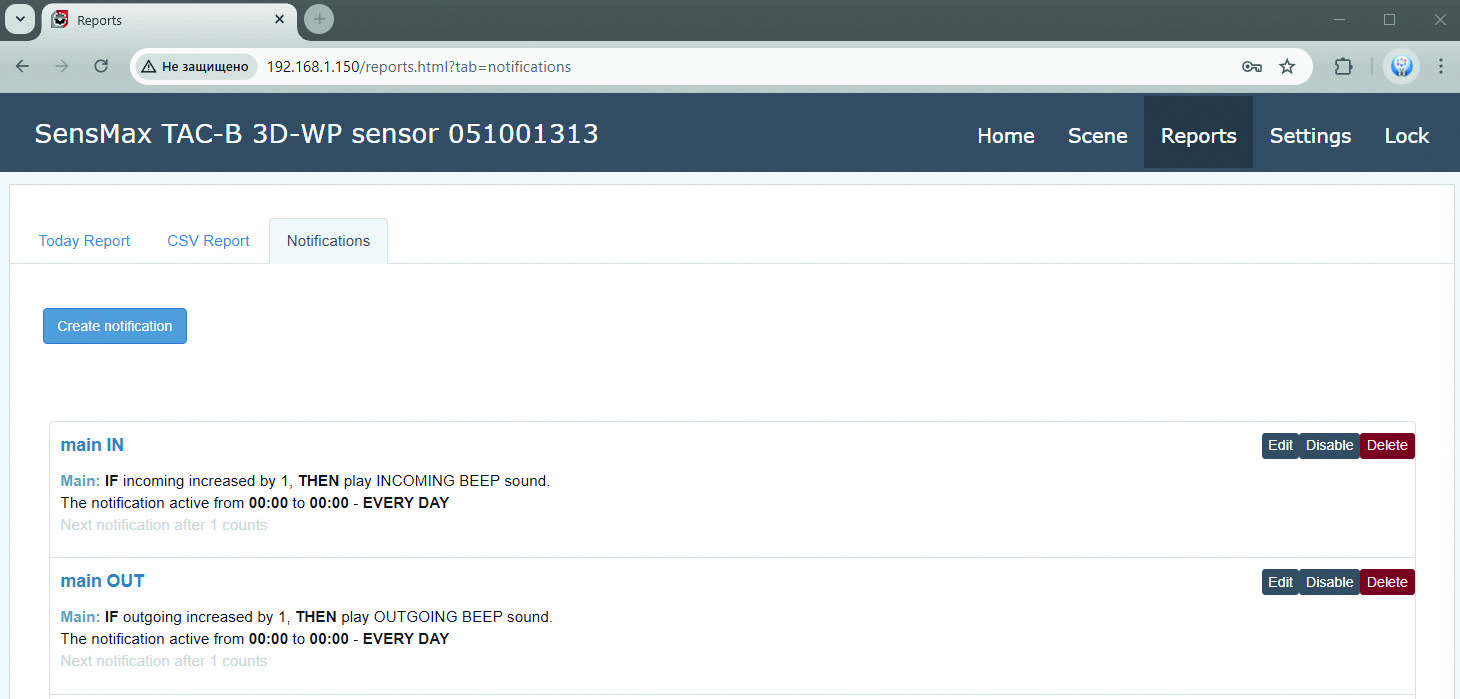
For creating of new notification, please press the Create button and setup desired parameters:
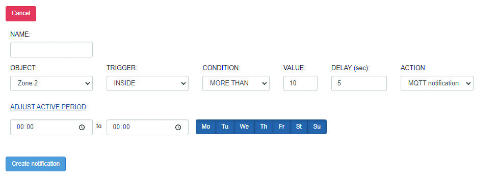
Table below describes the notification parameters:
| OBJECT | In this list all user defined object (gates and zones) are presented. Need to select one. |
|---|---|
| TRIGGER | Depending from object type (zone or gate) there will be allowed different triggers for selection. Supported triggers for the GATE: ƒ INCOMING (the count of incoming visitors) ƒ OUTGOING (the count of outgoing visitors) ƒ VISITORS ƒ PASSAGES ƒ ANY MOTION ƒ FIRST VISITOR (the first visitor for today) ƒ EVERY 5 MIN ƒ EVERY HOUR Supported triggers for the ZONE: ƒ INCOMING (the count of incoming visitors) ƒ OUTGOING (the count of outgoing visitors) ƒ VISITORS ƒ PASSAGES ƒ ANY MOTION ƒ FIRST VISITOR (the first visitor for today) ƒ EVERY 5 MIN ƒ EVERY HOUR ƒ INSIDE ZONE (number of objects currently inside the zone) ƒ ZONE IS EMPTY ƒ SOCIAL DISTANCE VIOLATION ƒ TOTAL OCCUPANCY TIME |
| CONDITION | In this list presented the type of conditions: MORE THAN and EVERY NEXT If MORE THAN selected, sensor will generate single notification when defined value will be reached. If EVERY NEXT selected, sensor will generate notification every time when counting result increases by defined value. |
| VALUE | The value which should be reached for trigger activation. |
| DELAY | This setting presented for the INSIDE trigger only. When the object count inside selected zone is more than defined value, this condition should stay during DELAY period before notification will be generated. |
| ACTION | Defines the notification type: Telegram notification, MQTT notification, Webhook launch or Sound Alert. |
Support of Webhooks
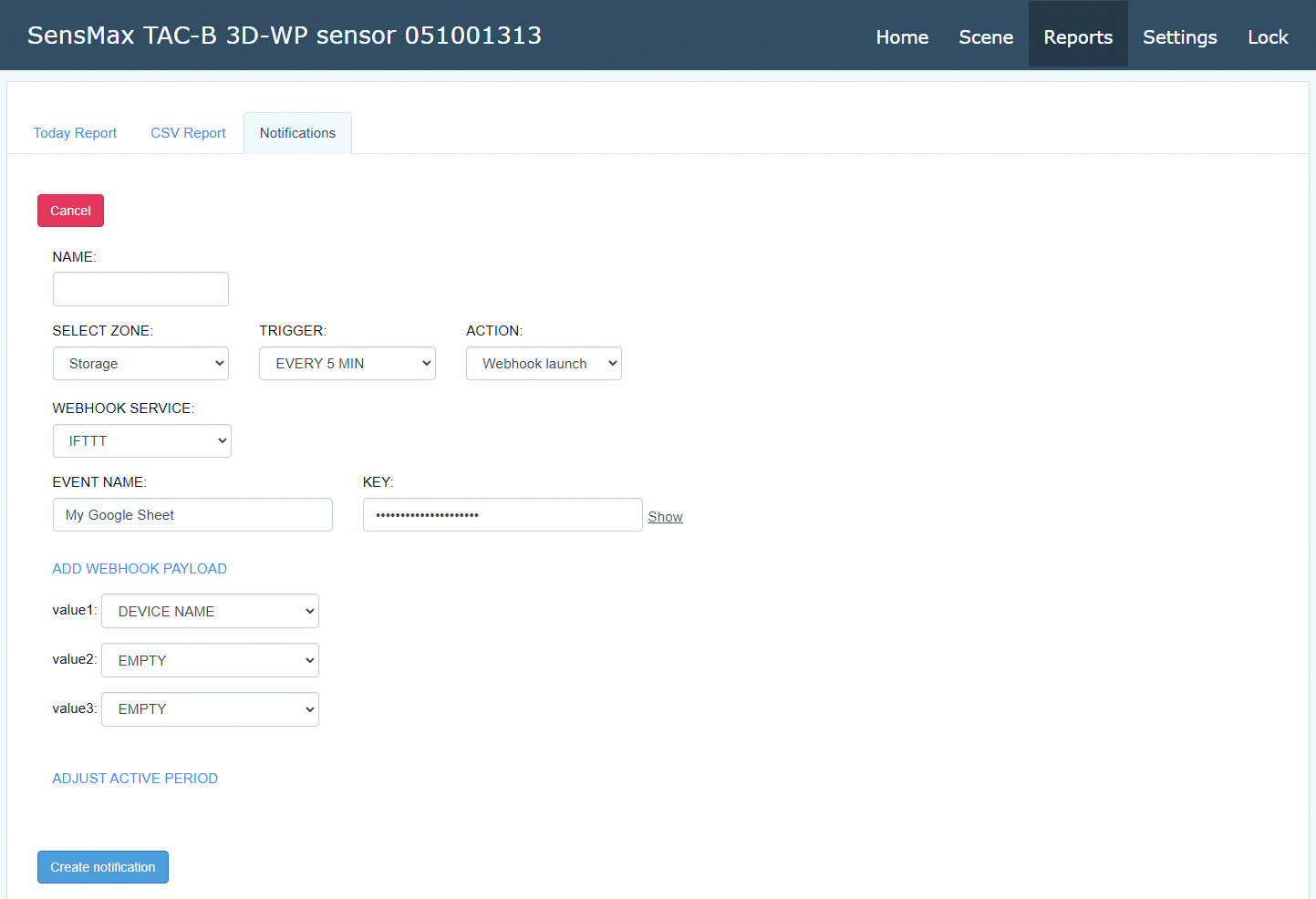
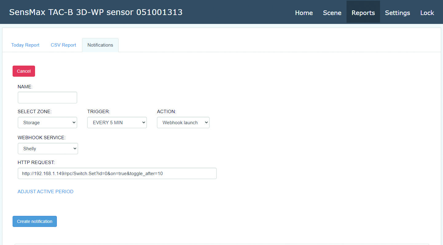
The sensor supports webhooks provided by IFTTT and Shelly services. Webhooks allow the sensor to send commands to different devices or send data to different services.
To use webhooks, need to select the Webhook launch in the ACTION field.
Example of notification creating for IFTTT:
Please refer to the IFTTT documentation for more information.
Example of notification creating for Shelly:
Please refer to the Shelly documentation for more information.
Ordering Information
Radar Sensors
| Model / Part Number | Description |
|---|---|
| SensMax TAC-B 3D-W | Indoor radar sensor (IP54, Wi-Fi) |
| SensMax TAC-B 3D-WP | Waterproof radar sensor for indoor/outdoor use (IP65, Wi-Fi, low-power features) |
| SensMax TAC-B 4G | Waterproof radar sensor for indoor/outdoor use with built-in 4G modem (IP65, Wi-Fi, 4G LTE, low-power features) |
Accessories
| Model / Part Number | Description | Compatible Sensors |
|---|---|---|
| TAC-B series mounting bracket | Special bracket for outdoor installation of TAC-B 4G or TAC-B 3D-WP sensors on a pipe (pole) or wall | SensMax TAC-B 3D-WP, SensMax TAC-B 4G |
| SensMax SPS20 solar power system | Solar power system for autonomous operation of SensMax TAC-B radar sensors | SensMax TAC-B 3D-WP, SensMax TAC-B 4G |
Contacts
- Phone: +371 67553110
- Email: office@sensmax.lv
- Website: www.sensmax.eu
- Telegram: t.me/sensmax
- Facebook: facebook.com/sensmaxmanufacturer
- LinkedIn: linkedin.com/company/sensmax
SensMax is a registered trademark. SensMax reserves the right to make changes to the products described herein without prior notice. The information contained in this publication regarding device applications and the like is provided solely for your convenience. SensMax disclaims all liability arising from this information and its use. The use of SensMax devices in life-support and/or safety-critical applications is entirely at the buyer's risk, and the buyer agrees to defend, indemnify, and hold harmless SensMax against any and all damages, claims, suits, or expenses arising from such use. No licenses are conveyed, implicitly or otherwise, under any intellectual property rights of SensMax.