SensMax TAC-B EWP Quick Start Guide
This manual will help you quickly prepare the radar sensor for operation. To familiarize yourself with all the specifications, port requirements, and full functionality, please refer to the Complete User Manual.
1. Connection and Power
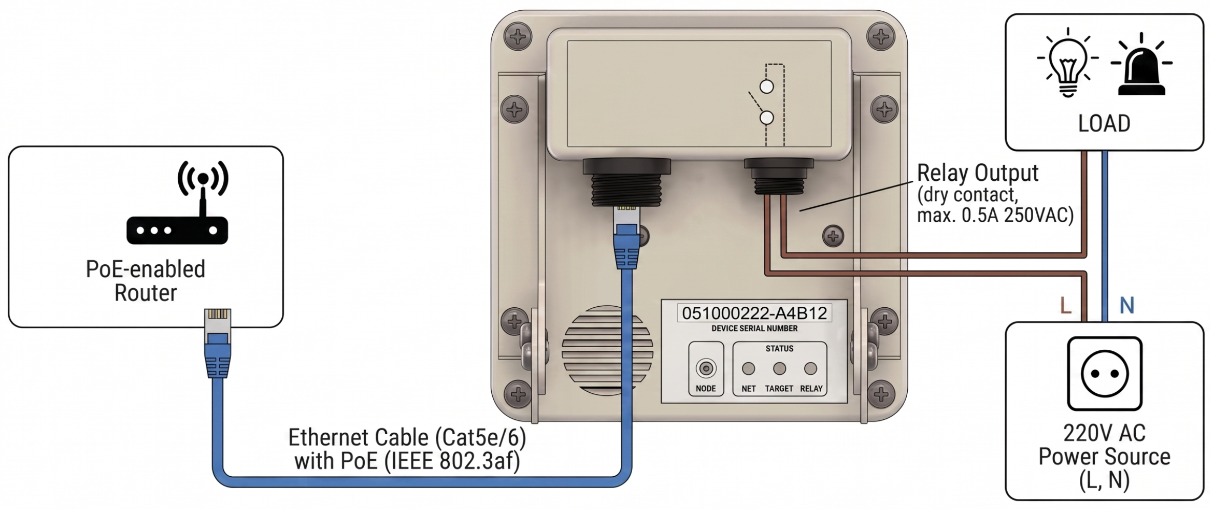
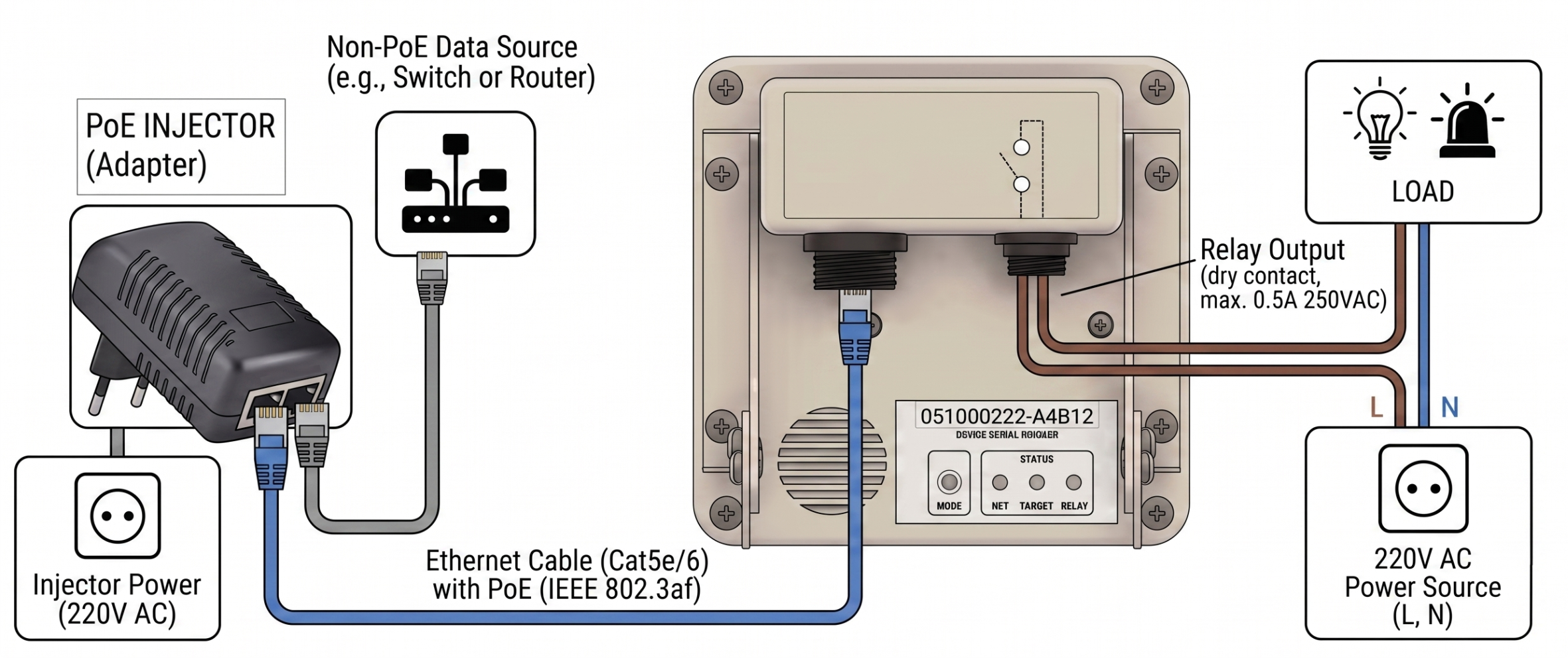
The sensor is powered and transmits data via a single Ethernet cable using PoE (Power over Ethernet) technology.
Connection diagram directly to a PoE router/switch:
Connection diagram using a PoE injector:
2. Mounting
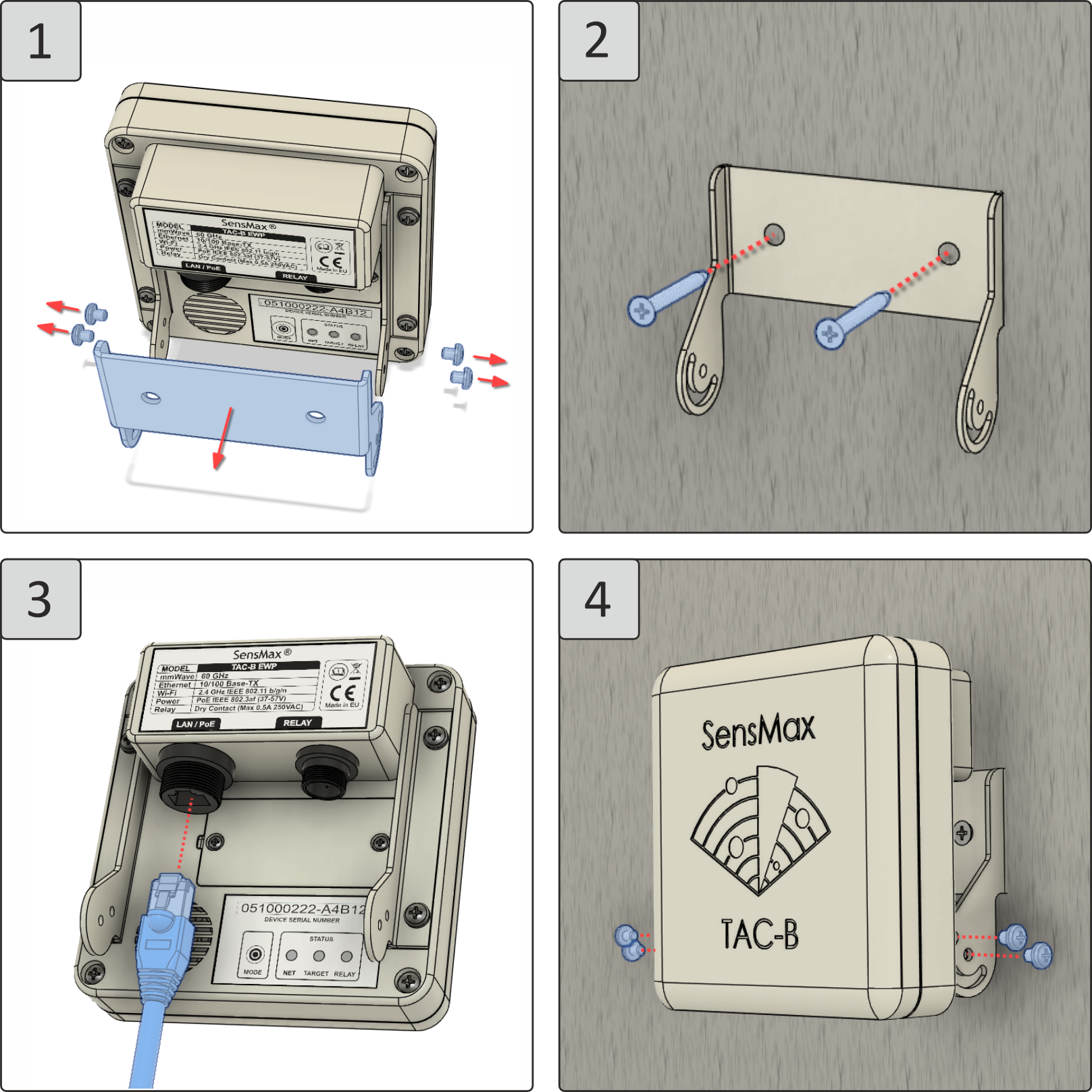
Secure the mounting plate (to the wall or ceiling) and install the sensor after previously connecting the cable. When mounting outdoors, use the weatherproof covers included in the kit.
Choose the correct height depending on the operating mode:
- Wall mode (Wall): Optimal installation height 2.5 - 3.5 m.
- Overhead mode (Overhead): Optimal installation height 2 - 3.5 m.
3. Positioning
After mounting the sensor, you need to position it according to the selected operating mode.
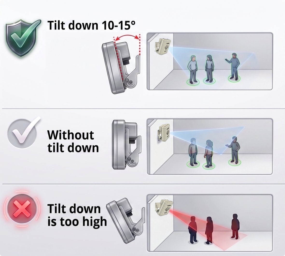
Positioning in wall mode
The radar beam should be directed above people's heads. The downward tilt angle is 10-15 degrees (if the installation height is more than 2 m).
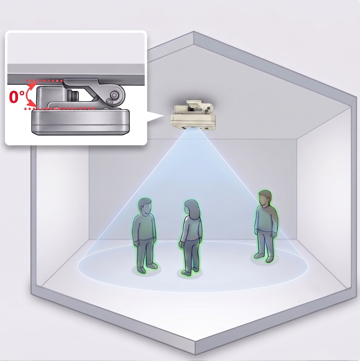
Positioning in overhead mode
In this mode, the sensor looks from top to bottom and registers objects directly below it. The sensor must be pointed straight down, with its plane parallel to the floor.
4. Logging into the Web Interface
Once the cable is connected, the sensor is ready for configuration. There are 2 connection options available:
- Via local network (mDNS): open
http://<serial_number>.localin your browser (e.g.,http://051001313.local). - Via built-in Wi-Fi access point: connect to a network like
SensMax TAC-B XXXXXXXXX(password is the serial number). Openhttp://192.168.10.1in your browser.
Authorization: The default password to enter settings is the device's serial number (numbers only).
5. Selecting the Operating Mode (Mode)
- In the web interface, go to the Settings page -> Mode tab.
- Select the desired operating mode.
- Specify the exact installation height from the floor (in centimeters) and click Save settings.
Warning
Switching modes takes about 2 minutes. Do not disconnect the power. Old zone and line settings are deleted when changing the mode.
6. Configuring Counting Zones or Lines
- In the sensor's web interface, go to the Scene section.
- Select the Edit counting zones tab.
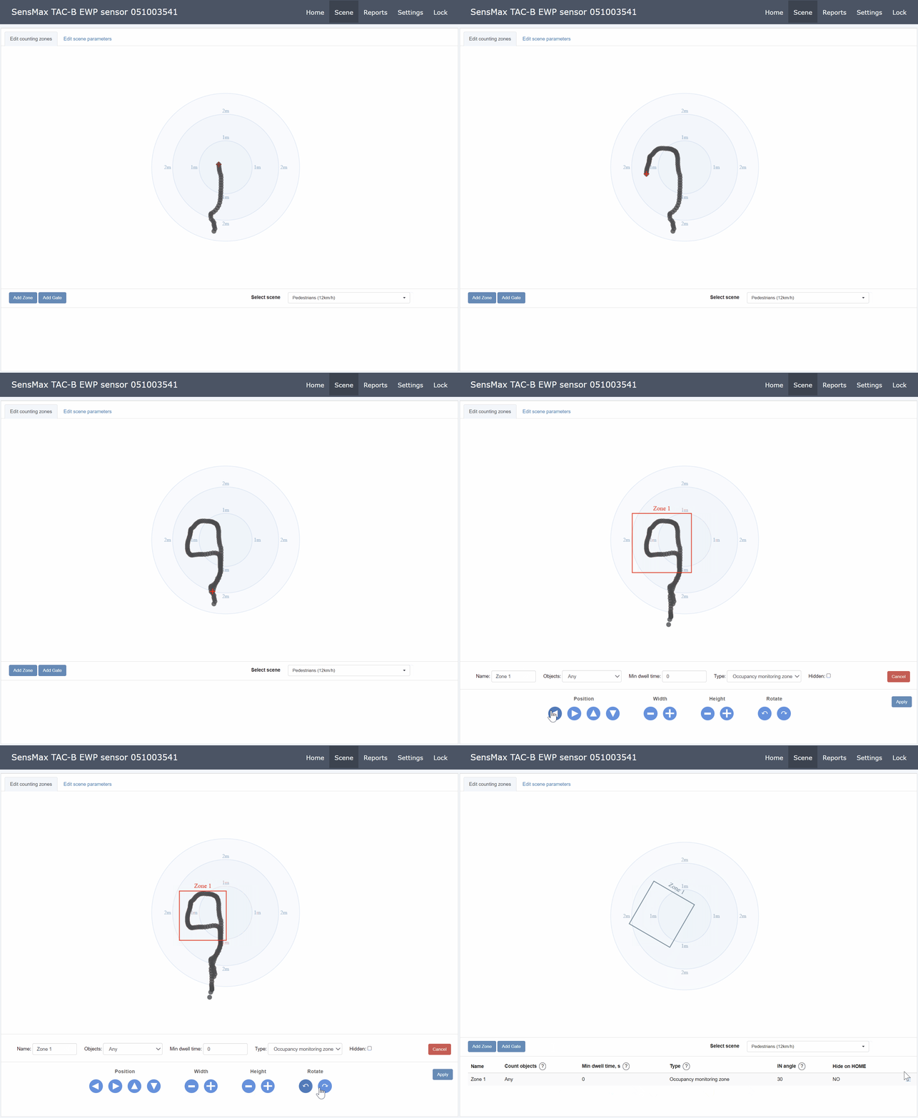
- Trajectory visualization: Walk through the actual area where counting is planned. Your route will be displayed on the interface screen as a trace (track).
- Placement: Click the Add Zone button (or Add Gate for lines). Guiding by the left trace, place the graphical counting zone or line exactly at the actual path of people.
- If necessary, adjust the zone size using the buttons at the bottom and save the changes.
7. Further Configuration
The device is basically configured! For detailed information on MQTT integration, setting up Telegram notifications, using the relay, and other features, read the Complete User Manual.
Contacts
- Phone: +371 67553110
- Email: office@sensmax.lv
- Website: www.sensmax.eu
- Telegram: t.me/sensmax
- Facebook: facebook.com/sensmaxmanufacturer
- LinkedIn: linkedin.com/company/sensmax
SensMax is a registered trademark. SensMax reserves the right to make changes to the products described herein without prior notice. The information contained in this publication regarding device applications and the like is provided solely for your convenience. SensMax disclaims all liability arising from this information and its use. The use of SensMax devices in life-support and/or safety-critical applications is entirely at the buyer's risk, and the buyer agrees to defend, indemnify, and hold harmless SensMax against any and all damages, claims, suits, or expenses arising from such use. No licenses are conveyed, implicitly or otherwise, under any intellectual property rights of SensMax.